Cyclone Leak Test Procedure
Version Name: CY-LK-TST
Version Number: 1.0
Effective Date: September 15, 1997
- Developed by:
- Raymond F. Feldman, Electronics Engineer, OSHA Technical Center
- Reviewed by:
- Sharon Anderson, Industrial Hygienist - Chicago, IL
- Nancy Christiana, Instructor - OSHA Training Institute
- Steve Edwards, Supervisory Chemist - OSHA Technical Center
- George Kilens, Assistant Area Director - Concord, NH
- Linda Lopez, Industrial Hygienist - Concord, NH
- Nancy Newman, Compliance Prog. Manager - Cleveland, OH
- Anthony Sutton, Industrial Hygienist - Chicago, IL
- Approved by:
- (Signature) (Date)
- Robert T. Williams, Director OSHA Technical Center Date
Table of Contents
- Section
- 1.
- INTRODUCTION AND DESCRIPTION
- 1.1
- Purpose
- 1.2
- Environmental and Operational Limits
- 1.3
- Test Method and Accuracy
- 1.3.1
- Tolerances and Limitations
- 1.3.2
- Summary of Test Method
- 1.3.3
- Description of Cyclone Assembly Parts
- 1.3.4
- Discussion of Test Method
- 2.
- EQUIPMENT REQUIREMENTS
- 2.1
- Equipment Listing
- 2.2
- Picture and Block Diagram of Equipment Set-up
- 3.
- PRELIMINARY OPERATIONS
- 3.1
- Safety Considerations
- 3.2
- Equipment Considerations
- 3.3
- Preliminary Steps
- 3.3.1
- Cyclone Preparation and Cleaning
- 3.3.2
- Test Equipment Preparation
- 4.
- LEAK TEST STEPS
- 4.1
- Nylon Parts Inspection
- 4.2
- O-Ring, Tubing, and Filter Leak Test
- 4.3
- Pump-Fault Test
- 4.4
- Data Record
- 5.
- SERVICE TIPS
- 6.
- DATA FORMAT
- Appendix A
- DISCUSSION OF TEST METHOD TOLERANCES AND LIMITATIONS
- Appendix B
- SUMMARY VERSION OF CYCLONE LEAK TEST PROCEDURE
- Figures
- Figure 1.1
- MSA Cyclone Assembly
- Figure 1.1a
- BDX 99R Cyclone Assembly
- Figure 1.2
- MSA Cyclone Assembly Parts
- Figure 1.2a
- BDX 99R Cyclone Assembly Parts
- Figure 1.3
- Metal Clamp (MSA Gravimetric Cyclones)
- Figure 1.4a
- MSA w/Clamp & Capped Tubing
- Figure 1.4b
- MSA w/Clamp & Rubber Plug
- Figure 1.4c
- MSA w/O-Ring & Capped Tubing
- Figure 1.4d
- MSA w/O-Ring & Rubber Plug
- Figure 2.1
- Leak Test Equipment Set-up with MSA Cyclone
- Figure 2.2
- Block Diagram of Leak Test Equipment Set-up
- Figure 5.0
- Sample of Typical Data Sheet
- Figure 5.0
- Blank Data Sheet
- Figure B-1
- Leak Test Equipment Set-up with MSA Cyclone
- Figure B-2
- Block Diagram of Leak Test Equipment Set-up (Same as Figure 2.2)
Cyclone Leak Test Procedure
SECTION 1
INTRODUCTION AND DESCRIPTION
1.1 PURPOSE:
This procedure describes a method of leak testing cyclone sampler assemblies. It is intended to reveal excessive leaks at the O-Rings, filter cassette, and tubing connections of the Cyclone assembly. It also prescribes a careful inspection of the Vortex Finder, Cyclone Body, Grit Pot, and the connections between these parts. A final check of the entire assembly is then provided using the pump fault mechanism. Leak testing of cyclone sampler assemblies is referenced in OSHA Directive TED 1.15, "The OSHA Technical Manual," Section I, Chapter 1, "Sampling Techniques."
1.2 ENVIRONMENTAL AND OPERATIONAL LIMITS:
No limitations need to be placed on the unit under test (UUT) or the test system operation regarding facility temperature, pressure, or humidity. No warm-up or initial stabilization time is needed.
1.3 TEST METHOD AND ACCURACY:
1.3.1 Tolerances and Limitations:
This procedure is designed to reveal excessive leaks at the connections between the Cyclone assembly parts. Aside from assuring a good fit between the nylon parts, testing for leaks in the parts between the pre-weighed filter input and the air sampling pump is the most important portion of the assembly to minimize leaks.
A 25% change in pressure gauge reading is used as the pass/fail criteria in the main part of this leak test procedure. When using the equipment setup described in this procedure, this criteria of 25% has been shown to be a good, achievable, and practical number for checking the general leakage in the cyclone assembly connections from the Vortex Finder to the air sampling pump, especially between the pre-weighed filter and the air sampling pump. Although a much higher leakage rate can be tolerated at the Plastic Filter Adaptor, the same 25% pass/fail criteria is applied to the whole chain of parts from the Vortex Finder to the air sampling pump.
In using the 25% pass/fail criteria it is very important that the total volume of air in the test system (including the pressure gauge internal volume) remains constant (approx. 335 cc). That is, if different test equipment is used for this test procedure which causes a change in the air volume of the test configuration, the pass/fail criteria must likewise be changed to a different number.
See Appendix 1 for a detailed discussion of the tolerances and limitations.
1.3.2 Summary of Test Method:
A comprehensive leak test of the Dorr-Oliver Cyclone assemblies can be accomplished by an inspection of the nylon parts for proper fit, applying a partial vacuum to the tubing-filter-adaptor-vortex combination and monitoring the leakage rate, and finally running the pump/cyclone assembly at 1.7 LPM and checking for a pump fault when the cyclone input is sealed closed. Sub-sections 1.3.2.1 through 1.3.2.3 summarize these three tests.
1.3.2.1 Nylon Part Inspection:
The Vortex Finder, Cyclone Body, and Grit Pot are inspected for wear, damage, scratches, and loose fitting connections which could contribute to leakage.
1.3.2.2 O-Ring, Tubing, and Filter Leak Test:
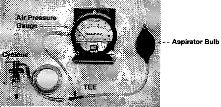
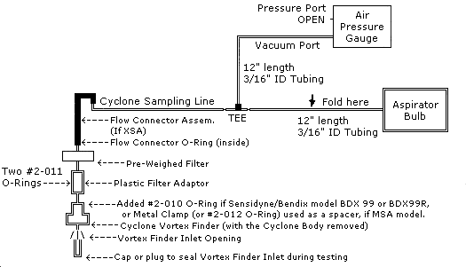
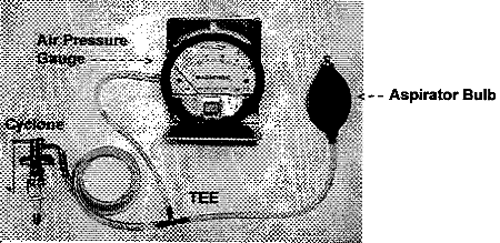
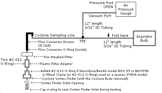
This test looks for leaks at the connections between the following parts: the Sampling Line, Flow Connector Assembly, Filter Cassette & filter, Plastic Filter Adaptor (or Coupler), and the Cyclone Vortex Finder. The equipment is connected as in Figures 2.1 and 2.2. An aspirator, or other means, is used to apply a partial vacuum of at least 4" H2O to the Cyclone assembly (Cyclone Body removed and the opening to the Vortex Finder blocked). The pressure reading is monitored for 30 seconds, and if the pressure reading changes less than 25% during this time, the leakage is acceptable and the unit passes the leak test.
Note: Leaks between the filter input and the air sampling pump are more disruptive than leaks at the Plastic Filter Adaptor O-Rings. If the primary leak is found to be upstream from the pre-weighed filter (e.g. at the plastic filter adaptor), a larger leak rate can be tolerated during the leak testing, since the normal operational pressure inside the Plastic Filter Adaptor is only 0.25" H2O compared to 2.5 - 37" H2O on the pump side of the filter.
1.3.2.3 Pump-Fault (Non-quantitative) Leak Test:
As a final test of the Cyclone Assembly, the assembly is connected in the normal sampling configuration with the air sampling pump running at 1.7 LPM. Then the inlet to the Cyclone is closed with tape or a finger. If the pump bears down and goes into a fault mode, the assembly passes the final but crude pump-fault leak test. Although this fault test and the nylon parts inspection might be performed more often than leak testing of the O-Rings and tubing, periodic testing as described in the previous section 1.3.2.2 is needed, too.
1.3.3 Description of the Cyclone Assembly Parts:
Figures 1.1 and 1.1a show the MSA and the Sensidyne/Bendix BDX 99R cyclone assemblies. Below them are Figures 1.2 and 1.2a showing the same assemblies disassembled and the parts identified.
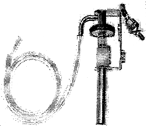
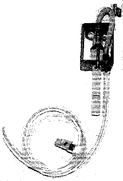
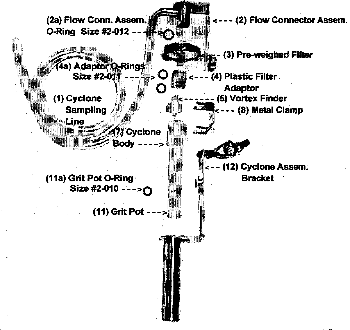

The following is a brief description of the cyclone assembly parts shown on the previous page in Figures 1.2 and 1.2a:
- Cyclone Sampling Line: the tubing that connects between the Cyclone assembly and the air sampling pump. This is the same tubing used with the Cyclone during sampling.
- Flow Connector Assembly (MSA Cyclone only): the metal flow connector assembly connects the Sampling Line to the Filter. On the filter end, there is a large O-Ring inside the Flow Connector Assembly which seals around the exhaust port of the filter.
The MSA Flow Connector Assembly O-Ring is size #2-012, 3/8" ID × 1/2" OD × 1/16" thick.
- Pre-weighed Filter: the filter cassette and filter supplied by the OSHA Technical Center. The side with the solid metal foil is the INLET side and connects to the plastic Filter Adaptor. The white side (or white with silver spokes) is the exhaust side and connects to the Flow Connector Assembly of the MSA Cyclone, or directly to the tubing of the Bendix Cyclone.
- Plastic Filter Adaptor: a 16 mm (5/8 inch) outside diameter, plastic cylinder which serves as a coupler between the Vortex Finder and the pre-weighed filter. The same Plastic Filter Adaptor can be used on both the MSA and Bendix Cyclones.
The Plastic Filter Adaptor has two O-Rings, both are size #2-011, 5/16" ID × 7/16" OD × 1/16" thick (same size as the Bendix Grit Pot O-Ring).
- Vortex Finder: the odd shaped nylon part which fits into the Cyclone body. The Vortex Finder has an exhaust fitting which is coupled to the filter with the "filter Adaptor".
- Vortex Finder Spacer O-Ring (Sensidyne/Bendix Cyclone only): an added O-Ring which fits over the Vortex Finder exhaust fitting and is seated in a groove on that fitting. This O-Ring part is provided by OSHA Technical Support to prevent the Vortex Finder Luer fitting from protruding too far into the pre-weighed filter. If the Vortex Finder fitting does not have a groove, contact the OSHA Technical Center about having them cut a groove in it with their lathe.
The Vortex Finder Spacer O-Ring is size #2-010, 1/4" ID × 3/8" OD × 1/16" thick (same size as the MSA grit pot O-Ring).
- Cyclone Body: the long nylon part about 8 cm long (3 inch) in which the Cyclone action takes place to separate the large and small particles.
- Metal Clamp (MSA Gravimetric Cyclones): a "C" shaped metal clip about 3 cm (1 1/8 inch) in length which holds the Vortex Finder properly positioned in the Cyclone Body during sampling. (See Figure 1.3).
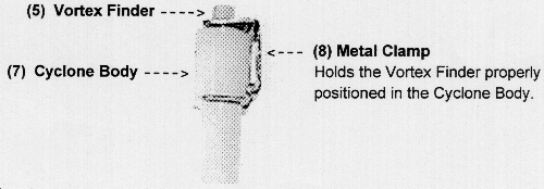
Figure 1.3 Metal Clamp (MSA Gravimetric Cyclones) - Clamp Substitution/Spacer O-Ring (for use during leak testing the MSA Cyclone): an O-Ring which can be placed over the Vortex Finder exhaust fitting of the MSA Cyclone in place of the Metal Clamp, in order to maintain the spacing between the Filter Adaptor and Vortex Finder during leak testing. The Metal Clamp, this O-Ring, or another type of spacer may be used as the spacer.
This spacer O-Ring can be a size #2-012, 3/8" ID × 1/2" OD × 1/16" thick (same as the MSA Flow Connector O-Ring).
The figures below, 1.4a thru 1.4d, show the test configuration of an MSA with the Metal Clamp and with the Clamp Substitution/Spacer O-Ring. Each is shown also with two different ways of sealing the Vortex Finger during the leak testing. It's your choice.
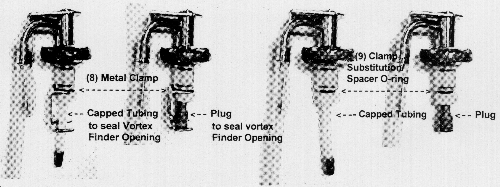
Figure 1.4a MSA w/Clamp & Capped Tubing
Figure 1.4b MSA w/Clamp & Rubber Plug
Figure 1.4c MSA w/O-Ring & Capped Tubing
Figure 1.4d MSA w/O-Ring & Rubber Plug
- Retainer (Sensidyne/Bendix BDX 99R Cyclones): a metal plate which fits over the Vortex Finder and is held in place with two screws. This retainer holds the Vortex firmly in the Cyclone body, and holds both of these items onto the Cyclone Assembly Bracket.
Note: The hole in the Retainer plate is too small for the Vortex Finder Spacer O-Ring. Therefore, the O-Ring must be removed from the Vortex Finder when installing or removing the Retainer plate. (A future design change in the BDX 99R to better accommodate the pre-weighed filter may simplify this.)
- Grit Pot: the short nylon part about 2 1/2 cm long (1 inch) which screws onto the Cyclone Body and collects the large dust particles which the cyclone rejects. An "O-Ring" helps seal this connection between the Grit Pot and the Cyclone Body.
The MSA Cyclone Grit Pot O-Ring is size #2-010, 1/4" ID × 3/8" OD × 1/16" thick. The Bendix Cyclone Grit Pot O-Ring is size #2-011, 5/16" ID × 7/16" OD × 1/16" thick.
- Cyclone Assembly Bracket and Hardware: a metal fixture designed to hold the Cyclone body, Vortex Finder, Filter Adaptor, Filter Cassette, and sampling line in place.
1.3.4 Discussion of Test Method:
The pressure difference between the inside of the Cyclone Assembly and atmospheric pressure outside the Cyclone Assembly increases for each stage of the Cyclone Assembly through which the air moves. Each restriction to the flow increases the pressure drop in that stage and in subsequent stages. The Cyclone Body and Vortex Finder offer very little resistance to the air flow, and the pressure decrease is very low. On the other hand, the filter is a large restriction, causing the pressure decrease (vacuum) after the filter to be much larger than in the Cyclone Body. As the filter collects more and more of the sample, the pressure drops even more.
Even though the pressure decrease (vacuum) in the Cyclone Body and Vortex Finder is small, it is important to keep the leaks to a minimum at the connection between the Cyclone Body and the Vortex Finder. Excessive leaks at this connection could disturb the cyclone pattern of the air flow in the Cyclone Body. Excessive leaks in the other connections of the Cyclone Assembly need to be kept to a minimum as well, since the cyclone operation depends on a given air flow rate through the Cyclone Body for proper operation. Leaks in the filter cassette and subsequent parts are important since the pressure drop in these parts can be as much as 37" H2O below that in the sampling environment. Leaks in the filter cassette and subsequent parts not only alter the effective flow rate, but can introduce dusty contaminants into the air sampling pump and possibly damage it.
A nominal pressure (vacuum) in each stage of the Cyclone assembly can be determined by measuring the effect each part of the Cyclone assembly had on the total loading of the air sampling pump. Keeping these different levels in mind helps in understanding the relative impact each leak can have on the functioning of the assembly. For an air flow rate of 1.7 LPM, the approximate pressure (vacuum) levels in a Dorr-Oliver Cyclone Assembly are:
- Inside the Cyclone Body:
- Between the Vortex Finder and the Filter:
- Between the Filter and the Air Sampling Pump:
- 0.15" H2O
- 0.25" H2O
- 2.5" H2O to 35" H2O
Note: The pressure between the Filter and the Air Sampling Pump depends on the amount of sample collected on the filter (but does not exceed the fault limit of the air sampling pump).
If the Vortex Finder, Cyclone Body, Grit Pot, and Grit Pot O-Ring are in good condition, and the Vortex Finder fits snugly into the Cyclone Body, leaks at these connections will be minimal. Since the pressure drop in the Cyclone Body is only 0.15" H2O, the importance of a good seal at these connections is primarily to assure the cyclone air flow pattern inside the Cyclone Body is not disturbed by the leaks. Just as important as a good fit, is the continued alignment of the Vortex Finder with the Cyclone Body. That is the purpose of the metal retainer clamp for the MSA unit and the screw-down retainer for the BDX 99R.
The O-Ring, Tubing, and Filter Leak Test test does not include the Cyclone Body or the Grit Pot which are inspected for proper fit and are included in the final general leak test. This test quantitatively checks the connections between the Sampling Line, Flow Connector Assembly, Pre-weighed Filter, Plastic Filter Adaptor, and the Cyclone Vortex Finder. The 4 - 10" H2O range used in this leak test procedure falls within the normal load range expected in a typical sampling session.
The volume of gas released through an opening is directly proportional to the size of the hole, the gas pressure, and the time lapsed, assuming the supply of gas is unlimited. If the container for the gas is limited by a fixed volume, the pressure will drop as the gas is released. The pressure in the fixed volume will change at a rate directly proportional to the size of the hole and the time that has lapsed, and inversely proportional to the size of the fixed volume supplying the gas. For a fixed volume and time, the leak can be measured by the percent drop in pressure for that given time duration.
This method of quantitizing leaks is limited, since any significant change in the air volume of the test configuration requires changing either the percentage limits or the measurement time. When using this procedure, the test volume must remain constant. That is why it is necessary to close off the test volume at the tubing between the aspirator bulb and the "Tee" fitting. Keeping the aspirator bulb in the measurement volume would significantly increase the test volume and alter the test results.
The final leak test is simple and straight forward, but only gives a general, non-quantitative, check for leaks that are so large that even the fault indicator of the air sampling pump fails to respond because of them. The primary purpose for this test is to provide a final leak test of the entire cyclone assembly, especially the parts upstream from the filter. It is only a general test which does not provide a quantitative measure, and does not adequately check the parts downstream from the filter. Periodic comprehensive leak testing should include all of the steps presented in this leak test procedure.
SECTION 2
EQUIPMENT REQUIREMENTS
This section describes the test equipment used to perform the leak tests described in this procedure.
2.1 EQUIPMENT LISTING:
- Air Pressure Gauge *
- Magnehelic, Dwyer Instrument Inc., P/N 2010 C, 0-10" H2O or equivalent.
- "T" fitting *
- Plastic or metal Tee fitting, suitable in size for connecting the tubing. The "TEE" in the leak test kit accepts both 3/16" and 1/4" tubing.
- Tubing *
- 2 pieces of Tygon or equivalent tubing: 3/16" ID, 1/16" minimum thickness, and approximately 12 inches long. The "Cyclone Sampling Line" is the same piece of tubing that will be used with the Cyclone when sampling.
- Aspirator bulb
- Dwyer A-350 or other way of generating the required partial vacuum.
- Timer
- Standard stopwatch or the second hand of a wrist watch (not included in kit).
2.2 PICTURE and BLOCK DIAGRAM OF EQUIPMENT SET-UP:
SECTION 3
PRELIMINARY OPERATIONS
3.1 SAFETY CONSIDERATIONS:
No special safety considerations are required for this procedure. If alcohol is used to help dry the inside of the Cyclone Body, be sure to observe all related safety precautions pertaining to its use.
3.2 EQUIPMENT CONSIDERATIONS:
The Dwyer pressure gauge is designed to take overloads. It is rated at 15 psi ( 415" H2O). Therefore, pegging the meter with a vacuum from the aspirator should not damage the meter.
3.3 PRELIMINARY STEPS:
3.3.1 Cyclone Preparation and Cleaning:
3.3.1.1. Unscrew the grit pot from the Cyclone. Empty the grit pot by turning it upside down and tapping it gently on a solid surface.
3.3.1.2 Inspect the Cyclone for dirt and clean it if needed. (The Cyclone parts should be cleaned thoroughly and gently after each use in warm soapy water, or washed in an ultrasonic bath.)
Caution: Never insert anything into the Cyclone that could scratch the inside surfaces. The Cyclone chamber is sensitive to scratches. A pipe cleaner might be used to clean out the hole in the Vortex Finder fitting, but do not use it on the inside of the cyclone body. A clean cotton tipped swab is well suited for cleaning the inside of the Cyclone Body, after first washing out any grit which could collect on the cotton tipped swab and scratch the nylon surface.
3.3.1.3 After cleaning the Cyclone Body, rinse it thoroughly in clean water, shake it to remove excess water, and set it aside to dry before reassembly.
Note: Isopropyl alcohol and cotton tipped swabs may be used to purge the inside of water. Alcohol will not harm the nylon and dries faster than water. Observe all safety precautions if alcohol is used in this way. Make certain the Cyclone is completely dry before using.
3.3.1.4 Record the Cyclone Leak Test Kit Pressure Gauge serial number on the data sheet, if used.
3.3.1.5 Record the Cyclone serial number, or identification, on the data sheet, if used. If the Cyclone has no form of identification, it is suggested that one be assigned and marked on the Cyclone for future reference, and the cyclone's parts be kept as a single unit.
3.3.2 Test Equipment Preparation:
This test of the pressure gauge (2010) is only necessary if you suspect a leak in the pressure gauge:
3.3.2.1. Connect the test equipment as in Figure 2.2, but leaving the Cyclone assembly disconnected.
3.3.2.2 With your finger over the open end of the "Tee" fitting, squeeze and release the aspirator bulb, and when the pressure gauge is reading a vacuum above 5" H2O, tightly fold the tubing between the "Tee" and the pressure gauge. If the reading is beyond full scale, release some of the vacuum (allow air in) until the reading is below full scale, but above midscale.
3.3.2.4 Observe the pressure gauge reading for about a minute. The needle should hold steady. If the reading drops more than a 1/2" H2O in a minute, the pressure gauge should be fixed.
SECTION 4
LEAK TEST STEPS
4.1 Nylon Parts Inspection:
The Vortex Finder, Cyclone Body, Grit Pot, and Grit Pot O-Ring are inspected for wear, damage, and loose fitting connections which could contribute to leakage.
4.1.1 With the Cyclone disassembled and cleaned as in section 3.3.1, inspect the Cyclone Grit Pot, Cyclone Body, and Cyclone Vortex Finder for cracks. Replace cracked parts.
4.1.2 Inspect how well the Cyclone Vortex Finder fits into the Cyclone Body. Compare with a new Cyclone, if possible. Replace worn or damaged parts that would cause excessive leaks.
4.1.3 Install the Cyclone Grit Pot and Grit Pot O-Ring onto the Cyclone Body, checking to assure they make a good seal with the Cyclone Body. If the O-Ring is damaged, replace it.
Note: Spare replacement O-Rings are contained in the accessory package which came with the leak test kit or can be obtained from the OSHA Technical Center:
The MSA Cyclone Grit Pot O-Ring is size 2-010, 1/4" ID × 3/8" OD × 1/16" thick.
The Bendix Cyclone Grit Pot O-Ring is size 2-011, 5/16" ID × 7/16" OD × 1/16" thick.
4.1.4 Record the results of this check (PASS/FAIL) on the data sheet, if used.
4.2 O-Ring, Tubing, and Filter Leak Test:
This test looks for leaks at the connections of the Sampling Line, Flow Connector Assembly, Pre-Weighed Filter, Plastic Filter Adaptor, and the Vortex Finder. A partial vacuum is applied to the Cyclone assembly (minus Cyclone Body) with the Vortex Finder sealed closed. The pressure is monitored for 30 seconds, and if the pressure reading changes less than 25%, the UUT passes.
4.2.1 Connect the Cyclone assembly to the pressure gauge and aspirator as shown in Figures 2.1 and 2.2, using the actual Cyclone parts that are to be used later at the survey site, including the same Cyclone Sampling Line.
Note: If the Sampling Line of an MSA Cyclone Assembly ever becomes disconnected from the Flow Connector Assembly, do not reconnect the stretched-out end of the tubing to Flow Connector Assembly. Cut off the stretched end, and then connect the new unstretched end to the metal shaft. When attached, the tubing should not move freely on the metal shaft.
MSA Cyclones: Be sure to install the Metal Clamp (or a #2-012 Clamp Substitution/Spacer O-Ring) over the Vortex Finder to keep the Plastic Filter Adaptor from fitting all the way down the port fitting of the Vortex Finder. (The Vortex Finder port fitting is slightly tapered, and testing with the Adaptor installed all the way onto the port fitting will seal the connection tighter than the normal configuration that is used during sampling. This might pass an otherwise leaky connection.)
Sensidyne/Bendix model BDX 99 or BDX 99R cyclones: A #2-010 O-Ring will fit onto the Vortex Finder port fitting and seat in a groove on the fitting. This added O-Ring prevents the metal part of the port fitting from extending too far into the pre-weighed filter. Be sure the #2-010 O-Ring is installed during the leak test, also. (The BDX 99R does not normally come with a groove in the Vortex Finder port fitting, but OSHA offices can request the OSHA Technical Center to cut a groove for them with their lathe.)
4.2.2 Seal the opening to the Cyclone "Vortex Finder" with a rubber or plastic cap, plugged up tubing, or by pressing the soft tissue of your finger over the hole. Whichever method is used, be sure to hold the assembly together with your hand, since the parts may leak more it they are not held in place.
Note: Rubber caps (hollow plug sleeve stoppers), or tubing capped at one end, are provided in the leak test kit accessory package to serve as plugs. Do not use putty or tape on this inside surface of the Vortex Finder; they leave sticky residues which can collect dirt and grit during sampling.
4.2.3 Squeeze and slowly release the aspirator bulb until the gauge reads between 4" H2O and 10" H2O vacuum, and then immediately fold (or clamp) the tubing between the "Tee" and the aspirator bulb.
If the vacuum reading is too high, release some of the vacuum at the Vortex Finder or at the fold in the tubing. Be patient. This may take a little practice.
Important Note: Remember to fold (or clamp) the tubing between the aspirator bulb and the "Tee". Do not rely on the Aspirator bulb valve to hold the vacuum. That would introduce the aspirator bulb into the test volume and change the results. Also, the aspirator valves can leak.
4.2.4 Observe and remember the pressure gauge reading. It will be recorded when your hands are free.
4.2.5 After 30 seconds, observe and record the pressure gauge reading again. If the vacuum dropped less than 25%, the unit passes the leak test.
Example: If the initial vacuum reading was 8" H2O, then 25% of 8" H2O. is 2" H2O. Thus the acceptable reading after 30 seconds would be a reading of 6" H2O or more.
If the pressure drops more than 25%, corrective action is necessary. This probably means one of the O-Rings is worn or damaged, the sampling line is cracked, the temporary seal at the Vortex Finder leaks, the pre-weighed filter leaks, or the pressure gauge leaks. If the primary leak is at the plastic filter adaptor, a much larger drop in the pressure gauge can be tolerated, since the normal pressure at the adaptor is just 0.25" H2O below the atmospheric pressure. (See Service Tips, Section 5.)
4.2.6 Record the results (PASS/FAIL) of this leak test on the data sheet, if used.
4.2.7 Remove the Filter Adaptor, rotate it so the opposite ends of the adaptor will connect at the filter and the Vortex Finder, reinstall the Filter Adaptor, and leak test again as in steps 4.2.2 through 4.2.6.
Note: The test described here in step 4.2.7 is not required if there is no chance the Filter Adaptor will be reversed during sampling (i.e., if one end is marked so it is obvious which end goes where).
4.3 Pump-Fault Test:
As a final test, the entire Cyclone assembly (including the Cyclone Body and Grit Pot) is connected in the normal sampling configuration, the air sampling pump is set to the normal sampling flow rate, and then the inlet to the Cyclone is sealed closed. If the pump bears down and goes into a fault mode, the assembly passes the final leak test.
4.3.1 Disconnect the Cyclone assembly sampling line from the "TEE" fitting and assemble the entire Cyclone Assembly (including the Cyclone Body and Grit Pot) in its normal sampling configuration to the air sampling pump.
4.3.2 Set the air sampling pump to RUN at a flow rate of 1.7 LPM ±0.2 LPM.
4.3.3 Place your finger or a piece of tape over the Cyclone inlet.
4.3.4 If the pump responds to the added load and faults, the Cyclone passes this test.
If the pump does not fault, either the Cyclone leaks excessively, or the pump is malfunctioning.
4.3.5 Record the results of this leak test including the serial number of the pump on the data sheet, if used.
4.4 Data Record:
A data sheet is provided with this procedure for optional use. Alternate methods of recording the results may be a record log, and/or on the OSHA -91A.
4.4.1 Record your name, the date, repairs, or any other comments on the data sheet, if used.
SECTION 5
SERVICE TIPS
5.1 If the Cyclone Assembly fails the main leak test of section 4.2, try leak testing each of the following configurations, watching for which added part causes an increase in the leak rate:
- Flow Connector Assembly and Cyclone Sampling Line only (MSA). (Seal with moist finger.) This tests for a good seal between the Sampling Line and the Flow Connector Assembly.
- Pre-weighed filter added. (Seal the filter opening with a moist finger or use the red plug that came with the Pre-weighed filter.) This will show if the Flow Connector Assem. O-Ring or the Pre-weighed filter is leaking. If this configuration does leak, try leak testing the Pre-weighed filter by itself. This will then tell you if the problem is the filter or the O-Ring.
- Plastic Filter Adaptor added. (Seal the Adaptor opening with a moist finger.) This configuration introduces one of the O-Rings of the Plastic Filter Adaptor.
- Vortex Finder and spacer added. (Seal the opening of the Vortex Finder as usual, being sure to hold the assembly together in one hand. Parts may leak more if the parts are not held in place.)
5.2 If the Plastic Filter Adaptor (coupler) is suspect, try reversing it. If the results change, then one of its O-Rings is worn. You can still use it, so long as one of the configurations passes, and the Plastic Filter Adaptor is not reversed during sampling (i.e., marked so it is obvious which end goes where).
If it fails both ways then both of the O-Rings may be worn, but first try replacing the Plastic Filter Adaptor with a new one, and check other items for leakage first before replacing both O-Rings.
If the seal is not improved by a new O-Ring, perhaps the groove inside the Adaptor is cut too deep. In that case, it may be necessary to replace the Adaptor.
The Plastic Filter Adaptor has two O-Rings, both size #2-011, 5/16" ID × 7/16" OD × 1/16" thick (the medium sized O-Ring in the accessory package, same size as the Bendix Grit Pot O-Ring).
5.3 A very likely source of leaks, especially with age, is the O-Ring in the MSA Flow Connector Assembly. This O-Ring is size #2-012, 3/8" ID × 1/2" OD × 1/16" thick (the largest O-Ring in the accessory package). Keep the old #2-012 O-Rings, since this size O-Ring can also be used during leak testing as a substitute spacer in place of the MSA Metal Clamp.
If the tests in step 5.1 show the leak is in the MSA Flow Connector Assembly, and replacing the O-Ring does not help, then the groove into which the O-Ring seats may be cut too deep. An O-Ring size #2-110 ( 3/8" ID × 9/16" OD × 3/32" thick ) may work in this situation.
5.4 If you need an O-Ring removal tool for the O-Rings that are seated inside the Filter Adaptor or the Flow Connector Assembly, dull the point of a safety pin (try scraping it on a file or a concrete walk) and bend the tip into a hook. This tool can then be used to hook under the O-Ring and pull it out of the recess. Avoid damaging the O-Ring when you remove it. If the O-Ring is found not to be worn, dried out, or damaged, it can be used again.
5.5 To test the Pre-weighed filter for leaks, connect it to the leak tester by itself using a piece of 1/4" ID tubing, seal the other end of the filter either with a moist finger or with the red plug that came with the filter, and check for leaks. If a pre-weighed filter fails the leak test, replace it.
5.6 Sometimes someone will remove the Sampling Line from the MSA Flow Connector Assembly. This should not be removed unless necessary. If the tubing (Sampling Line) has been removed and you are going to reconnect it, first cut off and discard the stretched out end. Then warm the new end of the tubing (can run hot water over the outside of the tubing), and stretch it over the flared end of the Flow Connector Assembly about 2 cm (or 3/4 inch) beyond the flared end. Assure the flared end of the Flow Connector Assembly makes a good seal with the tubing (i.e., the metal tube will not rotate inside the Sampling Line). Leak test this new connection before using.
SECTION 6
DATA FORMAT
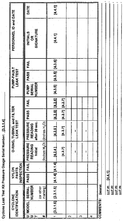
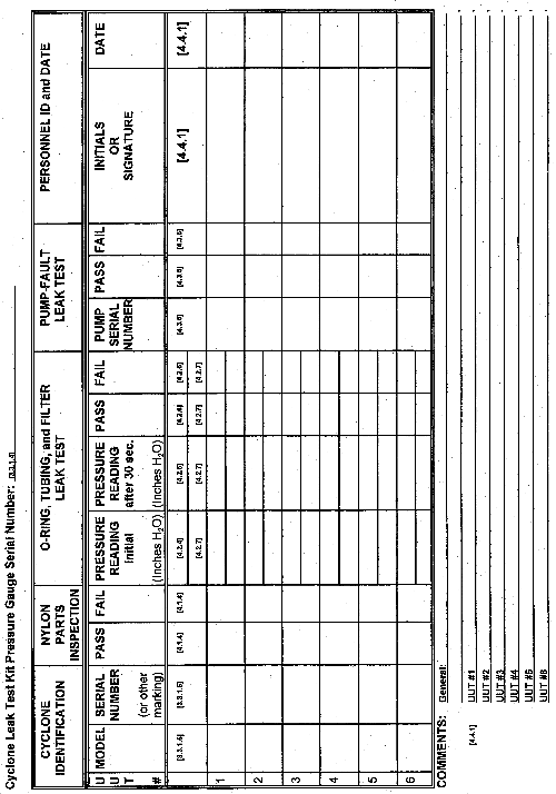
This sample data sheet shows the link between the data sheet and steps in the testing procedure. If the results are recorded, a blank data sheet is provided with this procedure which may be copied for optional use. Alternate methods of recording the results could be a record log, and/or on the OSHA -91A.
Appendix A
DISCUSSION OF TEST METHOD TOLERANCES AND LIMITATIONS
As stated in section 1.3.1, this procedure is designed to reveal excessive leaks at the connections between the parts of a Cyclone Assembly. Aside from a good fit between the nylon parts, the portion of the Cyclone Assembly between the pre-weighed filter input and the air sampling pump is the most important portion of the assembly to check for leaks. When using the test equipment setup described in this procedure, a 25% change in pressure gauge reading has been shown to be a good, achievable, and practical number to use for the pass/fail criteria in checking the general leakage in the cyclone assembly for parts between the Vortex Finder and the air sampling pump, especially between the pre-weighed filter and the air sampling pump. Since the normal operational pressure loading between the Vortex Finder and the Pre-Weighed Filter is independent of the loading of the filter by the collected sample, a much higher leak can be tolerated during leak testing between these parts, but for simplicity's sake, the 25% pass/fail criteria is applied to the whole chain of parts.
In the section of the cyclone assembly between the Pre-Weighed Filter and the air sampling pump, the pressure drop (vacuum) can range from 2.5" H2O when the filter is clean, to about 35" H2O when the filter is heavily loaded. This leak test assures that even under the extreme conditions of 35" H2O loading (very dirty filter), the effective nominal flow of 1.7 LPM would be reduced by less than 1% due to leakage.
When this leak test was developed, practical limits for the leak test were derived by examining new and used Cyclone assemblies. The procedure was tested by both laboratory and field personnel. The trial leak tests showed that new cyclones parts produced pressure gauge reading changes of less than 10% during a 30 second test period. Changes in pressure reading for UUTs with worn O-Rings exceeded 30%. Thus a 25% change in pressure gauge reading showed to be a good, achievable, and practical number to use for the pass/fail criteria. The question still remained, "Was that sufficient?"
Analysis of the test configuration provides interesting results. With the test volume sealed, a 5 cc change was induced in the test volume using a syringe to observe the resulting pressure gauge reading. The 5 cc volume change produced a change in the pressure gauge reading of approximately 6" H2O, and a 2.5 cc volume change produced a pressure reading change of 3" H2O. Now assume a leak test which begins with a 10" H2O reading and drops by 30% in 30 seconds. That would then represent a leakage of 2.5 cc per half minute at an average pressure of 8.5" H2O (average of the start pressure of 10" H2O and the ending pressure of 7" H2O). Restating this we could say that in using this leak test procedure, a 30% pressure gauge reading change during a period of one half minute from an initial 10" H2O reading represents a 5 cc per minute leak at 8.5" H2O. Proportionally, the same leak at 35" H2O would be 20.6 cc per minute (5 ÷ 8.5 × 35), or 1.21% of a 1.7 LPM air flow rate. To determine what leakage a 25% pressure change would represent, we would proportionally say a 4.16 cc volume change produces a 5" H2O change in pressure gauge reading (a 2.08 cc change produces as 2.5% change) and repeat the above logic. Thus, a 25% change from a 10" H2O reading represents a 16.6 cc per minute leak at 35" H2O (4.16 ÷ 8.75 × 35), or 0.98% of a 1.7 LPM air flow rate. A leakage of less than 1% under the heaviest loading sounds reasonable.
This procedure relies on measurement of pressure differences up to 10" H2O (inches of water). To avoid the mess associated with using a water manometer, a Dwyer Magnehelic pressure gauge is used to monitor the pressure (vacuum). Dwyer model 2010 has a full scale indication of 10" H2O (inches of water). A water manometer or other makes and models of pressure gauges may be used, but if the total volume of air in the test system (including the pressure gauge internal volume) is different from that described in this procedure (approx. 335 cc), different limits for the change rate of the pressure reading (or an adjustment in the air volume of the test configuration) would needed.
Note: The 5 cc analysis of the test configuration was performed when the atmospheric pressure was 999.1 mbar (401" H2O). With the temperature held constant, the volume of the test configuration can be calculated using P1V1 = P2V2 . Thus 401.1 × Vtest = (401.1 - 5.9) × (Vtest- + 5), which yields a value of Vtest = 335 cc, most of which is inside the pressure gauge. If a substitute pressure gauge has much less internal volume, the test configuration will be too sensitive to leaks, unless additional volume is added to the test configuration to compensate. Likewise, a pressure gauge with larger internal volume will be less sensitive to leaks, requiring a smaller percent change in pressure gauge reading for the pass/fail limit.
The Dwyer Magnehelic pressure gauge accuracy is guaranteed by Dwyer to be within ±2% of full scale. The OSHA Technical Center plans to calibrate these gauges on a periodic basis, but in applying this procedure, the absolute accuracy of the pressure gauge is not as important as the relative linearity between pressure levels, since the purpose of the pressure gauge is to compare a second reading relative to an initial reading. As long as the gauge's relative linearity is reliable, an absolute uncertainty of ±10% at the full scale reading is more than adequate.
The final Pump-Fault leak test described in this procedure primarily checks the parts upstream from the filter, i.e., the Filter Adaptor, Vortex Finder, and Cyclone Body. To fail this leak test the total leaks must amount to 95% or more of the 1.7 LPM setting while under near fault loading of the pump and all of the Cyclone parts. Under normal operating conditions all of the parts are not subjected to such extreme loading. Assuming a 37" H2O fault level for the pump, the estimated leakage which would occur under normal operating conditions for a cyclone assembly failing this test would be greater than 6.7-100% (2.5/37 to 37/37) between the filter and the pump, or 0.7% (0.25/34.5) at the Filter Adaptor, or 0.4% (0.15/34.4) at the Vortex Finder and Cyclone Body connection. These percentages were calculated by dividing the normal loading at that location by the minimum loading needed at that point to cause a pump fault, times 100 percent.
Appendix B
SUMMARY VERSION OF Cyclone LEAK TEST PROCEDURE
Read the entire procedure before using this summary list to leak test the cyclone. This summary is provided for the convenience of those who have already read and are familiar with the procedure. A copy of this page may serve as a checklist for the principle steps of the procedure.
PREPARATION and INSPECTION:
- Disassemble the Cyclone assembly, clean it, and inspect it for cracks and worn fit between parts. Never insert anything into the Cyclone which will scratch the inside surface of the Cyclone chamber.
- Replace the units or parts if they are worn or have any cracks.
O-RING, TUBING, and FILTER LEAK TEST:
- Connect the entire Cyclone assembly (minus the Cyclone Body) to the pressure gauge and aspirator, maintaining the normal spacing between the Plastic Filter Adaptor (coupler) and the Vortex Finder.
- Seal the Cyclone "Vortex Finder" opening by placing an airtight cap or your finger tip over the hole.
- Hold the Cyclone Assembly together with one hand.
- With your other hand, squeeze and gently release the aspirator bulb until the pressure gauge reads between 4" H2O and 10" H2O, then fold the tubing halfway between the "Tee" fitting and the aspirator. This takes practice. If the pressure reading is beyond full scale, release the vacuum and try again.
- Observe the pressure gauge reading for 30 seconds.
If the pressure drops less than 25%, the unit passes the main leak test.
Note: If the pressure drops more than 25%, corrective action is necessary. Probable sources of leaks are: worn or damaged O-Rings, cracked or ill-fitting tubing, leaky pre-weighed filter cassette, or air getting at the "Vortex Finder" opening.
FINAL FAULT TEST:
- Connect the complete Cyclone assembly to the pump in the normal sampling configuration at 1.7 LPM.
- Block the Cyclone inlet hole, and if pump faults, the cyclone passes this final assembly test.
