[Federal Register: December 29, 2005 (Volume 70, Number 249)][Rules and Regulations]
[Page 76979-77025]
From the Federal Register Online via GPO Access [wais.access.gpo.gov]
[DOCID:fr29de05-4]

=======================================================================
-----------------------------------------------------------------------

DEPARTMENT OF LABOR

Occupational Safety and Health Administration

29 CFR Parts 1926 and 1928

[Docket No. S-270-A]
RIN 1218-AC15

Roll-Over Protective Structures

AGENCY: Occupational Safety and Health Administration (OSHA), DOL.

ACTION: Direct final rule.

-----------------------------------------------------------------------

SUMMARY: In 1996, OSHA published a technical amendment revising the
construction and agriculture standards that regulate testing of roll-
over protective structures (``ROPS'') used to protect employees who
operate wheel-type tractors. This revision removed the original ROPS
standards and replaced them with references to national consensus
standards for ROPS-testing requirements. The Agency believed that the
national consensus standards essentially duplicated the ROPS standards
they replaced, and that any differences between them were not substantive.
Subsequently, OSHA identified several substantive differences between the
national consensus standards and the original ROPS standards. Therefore,
the Agency is reinstating the original ROPS standards by issuing this
direct final rule. The reinstated ROPS standards for both construction
and agriculture also contain a number of minor revisions that OSHA
believes are not substantive and will improve comprehension of, and
compliance with, the standards.

DATES: This direct final rule will become effective on February 27,
2006 unless significant adverse comment is received by January 30,
2006. If OSHA receives significant adverse comment, it will publish a
timely withdrawal of this rule. Submit comments to this direct final
rule by the following dates:
    Hard copy: Submit (i.e., postmarked or sent) comments by regular
mail, express delivery, hand delivery, and courier service by January
30, 2006.
    Electronic transmission and facsimile: Submit comments by January
30, 2006.
    The incorporation by reference of specific publications listed in
this direct final rule is approved by the Director of the Federal
Register as of February 27, 2006.

ADDRESSES: Submit written comments to this direct final rule--
identified by docket number S-270-A or RIN number 1218-AC15--by any of
the following methods:
     Federal eRulemaking Portal: http://www.regulations.gov.
Follow the instructions for submitting comments.
     OSHA's Web site: http://dockets.osha.gov/. Follow the
instructions for submitting comments.
     Facsimile: When written comments are 10 pages or fewer,
fax them to the OSHA Docket Office at (202) 693-1648.
     Regular mail, express delivery, hand delivery, and courier
service: Submit three copies to the OSHA Docket Office, Docket No. S-
270-A, U.S. Department of Labor, 200 Constitution Avenue, NW., Room N-
2625, Washington, DC 20210; telephone: (202) 693-2350. (OSHA's TTY
number is (877) 889-5627.) Please note that security-related problems
may result in significant delays in receiving comments and other
written materials by regular mail. Telephone the OSHA Docket Office at
(202) 693-2350 for information regarding security procedures concerning
delivery of materials by express delivery, hand delivery, and messenger
service. The hours of operation for the Docket Office are 8:15 a.m. to
4:45 p.m., EST.
    Additional materials: When a commenter would like to submit
additional materials (e.g., studies, journal articles) to supplement
comments that were submitted electronically or by facsimile, these
materials must be sent, in triplicate hard copy, to the OSHA Docket
Office, Technical Data Center, Room N-2625, OSHA, U.S. Department of
Labor, 200 Constitution Ave., NW., Washington, DC 20210. These
materials must clearly identify the sender's name, date, subject, and
docket number (S-270-A) or RIN number (1218-AC15) to enable the Agency
to attach them to the appropriate comments.
    Personal information: OSHA will make available to the public,
without revision, all comments and other materials submitted to the
docket, including any personal information. Therefore, the Agency
cautions commenters about submitting statements they do not want made
available to the public, or submitting comments that contain personal
information (either about themselves or others) such as social security
numbers, birth dates, and medical data.

FOR FURTHER INFORMATION CONTACT: For general information and press
inquiries, contact Mr. Kevin Ropp, Director, Office of Communications,
OSHA, U.S. Department of Labor, Room N-3637, 200 Constitution Avenue,
NW., Washington, DC 20210; telephone: (202) 693-1999; fax: (202) 693-
1634. For technical inquiries, contact Mr. Mark Hagemann, Acting
Director, Office of Safety Systems, OSHA, U.S. Department of Labor,
Room N-3609, 200 Constitution Avenue, NW., Washington, DC 20210;
telephone: (202) 693-2255; fax: (202) 693-1663. For detailed
instructions on submitting comments and for additional information on
the rulemaking process, see the ``Public Participation'' heading under
the section below titled Supplementary Information.

SUPPLEMENTARY INFORMATION:

Table of Contents

I. Direct Final Rulemaking
II. Summary and Explanation of the Rulemaking
    A. Basis for the Rulemaking
    B. Substantive Differences Between the Standards
    C. Minor Revisions to the Original OSHA ROPS Standards
III. Procedural Determinations
    A. Legal Considerations
    B. Economic Analysis and Regulatory Flexibility Certification
    C. Paperwork Reduction Act
    D. Federalism
    E. State-Plan States
    F. Unfunded Mandates Reform Act
    G. Public Participation
List of Subjects
Authority and Signature
IV. Amended Standards

I. Direct Final Rulemaking

    The Agency uses direct final rulemaking when it expects that a rule
will not be controversial. Examples of such rules include minor
substantive revisions to regulations, incorporation by reference of the
latest edition of a technical or industry consensus standard, and
direct incorporations of mandates from new legislation. In direct final
rulemaking, OSHA publishes a final rule in the Federal Register with a
statement that, unless it receives a significant adverse comment by a
specified date, the rule will become effective on a designated date
thereafter.
    OSHA believes that the subject of this rulemaking is suitable for a
direct final rule. The Agency bases this decision on substantive
differences found between the original OSHA standards on roll-over
protective structures (``ROPS'') for the construction and agriculture
industries and the national consensus standards issued by the Agency
under a 1996 technical amendment to replace the original standards. By
replacing the original ROPs testing provisions through a technical
amendment, OSHA denied the regulated community an opportunity for
notice-and-comment on these substantive differences as required under
the Administrative Procedures Act (5 U.S.C. 553(b)) and the
Occupational Safety and Health Act of 1970 (29 U.S.C. 655(b)(2) and
(b)(3)). Therefore, the Agency has concluded that it has a legal
obligation to the regulated community to reinstate the original OSHA
standards through this direct final rule. (See section II.A below
(``Basis for the Rulemaking'') for a detailed discussion of the
Agency's legal analysis of this issue.)
    Having concluded that this reinstatement action constitutes a
binding legal obligation, the Agency will consider as significant
adverse comments only those comments that address: (1) The lawfulness
of the procedures used to promulgate the 1996 technical amendment as
these procedures relate to the ROPs testing provisions; and (2) whether
the minor revisions made to the original ROPS standards in this direct
final rule (see a description of these revisions under section II.C of
this preamble) are reasonable or appropriate.
    The Agency often publishes an identical proposed rule
simultaneously with a direct final rule. In this instance, however, OSHA
is not publishing a companion proposed rule. Should OSHA receive any
significant adverse comments to this direct final rule, it will
withdraw the rule and determine, based on the comments submitted to the
record, whether to issue a proposed rule in the future. Accordingly, if
OSHA receives timely significant adverse comments on the two issues
described in the previous paragraph, it will publish notice of the
significant adverse comments in the Federal Register and withdraw this
direct final rule no later than February 27, 2006.

II. Summary and Explanation of the Rulemaking

A. Basis for the Rulemaking

    On March 7, 1996, OSHA published a technical amendment in the
Federal Register that revised a number of its standards. Section II.G
of the amendment revised the construction and agriculture standards
that regulate testing of roll-over protective structures (``ROPS'');
employers use these structures to protect employees who operate wheel-
type tractors. (See 61 FR 9228.) ROPS testing determines the capacity
of ROPS components to absorb energy (i.e., withstand fracturing) during
loadings administered under field and/or laboratory conditions, and
under different temperature conditions. The revision removed the
original, detailed ROPS-testing standards and referred instead to
national consensus standards for substantive ROPS-testing requirements.
The 1996 technical amendment was part of an OSHA initiative to
``undertake a line-by-line review of * * * regulations to determine
where they could be simplified or clarified'' (61 FR 9228).
    The Administrative Procedures Act (APA) (5 U.S.C. 553(b)), the
Occupational Safety and Health Act of 1970 (OSH Act) (29 U.S.C.
655(b)(2) and (b)(3)), and OSHA's procedural regulations (29 CFR
1911.5) require that OSHA provide notice and an opportunity for comment
during substantive rulemaking. However, in the preamble to the 1996
technical amendment, the Agency noted that the technical amendment did
not revise the original ROPS standards in any material fashion, and
that ``[t]he substantive requirements are unchanged'' between the
original ROPS standards and the consensus standards that replaced them
(61 FR 9229). For this reason, OSHA determined that the technical
amendment did not require notice and an opportunity for comment because
it satisfied the ``unnecessary'' exemption specified by the APA (5
U.S.C. 553(b).\1\ Relying on the ``unnecessary'' exemption to notice
and comment, the Agency stated:
---------------------------------------------------------------------------

    \1\ The three exemptions Specified by this provision of the APA
are: Impracticable, unnecessary and contrary to the public interest.

    OSHA has determined that this rulemaking is not subject to the
procedures for public notice-and-comment rulemaking specified under
section 4 of the Administrative Procedure Act (5 U.S.C. 553) or sec.
6(b) of the Occupational Safety and Health Act of 1970 (29 U.S.C.
655(b)) because this rulemaking does not affect the substantive
requirements or coverage of the standards involved. This rulemaking
does not modify or revoke existing rights and obligations, and new
rights and obligations have not been established. Under this
rulemaking, the Agency is merely correcting or clarifying existing
regulatory requirements. OSHA therefore finds that public notice-
and-comment procedures are unnecessary within the meaning of 5
---------------------------------------------------------------------------
U.S.C. 553(b)(3)(B) and 29 CFR 1911.5. (61 FR 9229.)

    Several years after issuing the 1996 technical amendment, the
Agency was informed that several of the original OSHA ROPS provisions
differed substantively from the national consensus standards for the
construction and agriculture industries (Ex. 4-7). In response to this
information, the Agency conducted a thorough evaluation of its original
ROPS standards and the ROPS testing requirements contained in the
national consensus standards referenced in its current construction and
agriculture ROPS standards. OSHA has included in the docket for this
rulemaking four side-by-side comparisons of the differences found
between the original OSHA standards and the referenced national
consensus standards (Exs. 4-1 to 4-4).
    Based on the findings of this evaluation, which are described in
detail in the following section, the Agency has concluded that
differences do exist between its original construction and agriculture
ROPS standards and the ROPS standards implemented under the 1996
technical amendment, that these differences have a substantial impact
on the regulated community, and that OSHA incorrectly applied the APA's
``unnecessary'' exemption to the ROPs testing procedures. This
conclusion is consistent with existing case law. For example, in
Utility Solid Waste Activities Group v. Environmental Protection
Agency, 236 F.3d 749 (D.C. Cir. 2001), the court found that an EPA
technical amendment had a significant impact on the regulated community
and, most importantly, that it did not meet any of the three exemptions
to notice-and-comment rulemaking specified by the APA i.e., 5 U.S.C.
553(b)(B) (Id. at 754)). In vacating the technical amendment, the court
stated, ``The amendment * * * constituted agency action `without
observance of [the] procedure required by law' and, as such, it is
`unlawful and set aside.' 5 U.S.C. 706(2)(D).''
    The substantive differences found between the standards and the
legal analysis described in the preceding paragraphs support the
Agency's conclusion that reinstating the original OSHA standards
through this direct final rule is necessary and appropriate.
Specifically, the Agency is revoking the references to the national
consensus standards for ROPS testing located in paragraphs 29 CFR
1926.1002(a)(i), 1926.1003(a)(i), and 1928.51(b)(1) and reinstating in
the construction and agriculture standards the original OSHA ROPS
testing provisions. For both the reinstated construction and
agriculture ROPS standards, the Agency also has made a number of minor
revisions to its original ROPS standards. OSHA believes that these
minor revisions will improve comprehension of, and compliance with, the
reinstated standards without making substantive revisions.
    The following section highlights the substantive differences
between its original ROPS testing requirements and the testing
provisions of the consensus standards referenced in its current ROPS
construction and agriculture standards. The Agency describes in section
II.C below the minor revisions it is making to the original OSHA ROPS
standards under this direct final rule.

B. Substantive Differences Between the Standards

    Construction standards. In revising the ROPS standards for
construction in the 1996 technical amendment, the Agency deleted
paragraphs (c) through (i) and (k) from 29 CFR 1926.1002, which
addressed testing of protective frames for wheel-type tractors used in
construction, and replaced them with a reference to Society of
Automotive Engineers (``SAE'') consensus standard J334a-1970 in
paragraph (a)(1) of revised 29 CFR 1926.1002. The Agency also revised
29 CFR 1926.1003, specifying testing requirements for overhead
protection used with tractors, by removing paragraphs (c) through (g)
and substituting a reference to SAE consensus standard J167-1970 in
paragraph (a)(1) of the revised standard.
    While most of the revisions to the construction ROPS standards made
in the 1996 technical amendment were nonsubstantive, the Agency
identified two substantive revisions. The first revision involved
paragraph (c)(1) of original 29 CFR 1926.1002, which allowed the regulated
community to use either a laboratory test or a field test for impact testing,
while the SAE standard requires both tests. Accordingly, this direct final
rule reinstates the impact-testing option provided by paragraph (c)(1)
of original 29 CFR 1926.1002, and which is not available in the SAE
standard. (See Ex. 4-1.)
    The second revision addressed paragraphs (i)(ii) of original 29 CFR
1926.1002 and (f)(1) of original 29 CFR 1926.1003, in combination with
paragraph (f)(2)(iv) of 29 CFR 1926.1001. These paragraphs permitted
manufacturers to conduct the required performance tests using either
zero-degree Fahrenheit (0 [deg]F) testing or Charpy V-notch testing,
while the SAE standard specifies that performance tests must be
conducted only at 0 [deg]F.\2\ Therefore, reinstating the original OSHA
standards will provide an additional cold-temperature testing option
not available in the SAE standard. (See Exs. 4-1 and 4-2.)
---------------------------------------------------------------------------

    \2\ These two tests determine, under controlled laboratory
conditions, the reduced-temperature ductility of the carbon steel
used to make ROPS. Generally, the less ductile the steel, the more
likely it is to fracture with impact during reduced-temperature
exposure (thereby losing its protective features). The 0 [deg]F
test, used principally by ROPS manufacturers, involves administering
impacts and/or loads to the entire ROPS at 0 [deg]F, while the
Charpy V-notch test, used primarily by steel manufacturers, applies
impacts to steel specimens of a predetermined size at several
reduced-temperature levels.
---------------------------------------------------------------------------

    Agriculture standards. In revising the ROPS standards for the
agriculture industry, the Agency deleted entirely original 29 CFR
1928.52 and 1928.53, as well as Appendix B to subpart C of 29 CFR part
1928. The deleted standards specified procedures for testing,
respectively, protective frames and enclosures for wheel-type tractors
used in agriculture, while Appendix B provided diagrams depicting these
testing procedures. In place of these requirements, OSHA referenced SAE
consensus standard J334a-1970 and American Society of Agricultural
Engineers (``ASAE'') consensus standard S306.3-1974 for protective
frames, and SAE consensus standard J168-1970 and ASAE consensus
standard S336.1-1974 for protective enclosures, in paragraph (b)(1) of
revised 29 CFR 1928.51.
    For both protective frames and protective enclosures, the testing
conducted under the ASAE and SAE standards generally is consistent with
the testing requirements of the original OSHA standards. However, the
Agency found several substantive differences between the original OSHA
standards and the consensus standards (for testing both protective
frames and protective enclosures) that replaced them. First, both the
original OSHA standards and the ASAE standards differ substantively
from the SAE standards by providing an exemption from field-upset
testing based on results for either the static or dynamic versions of
the laboratory energy-absorption test,\3\ while the SAE standards
require field-upset testing only under dynamic test conditions.
Consequently, this direct final rule will reinstate the testing
exemption found in the original OSHA ROPS standards. (See Exs. 4-3 and
4-4.) Second, the original OSHA and the SAE standards allow either
static or dynamic testing at 0 [deg]F, while the ASAE standards limit
testing at 0 [deg]F to dynamic testing. Therefore, reinstating the
original OSHA standards under this direct final rule restores the
testing option found in the original OSHA standards, but which is not
in the ASAE standards. (See Exs. 4-3 and 4-4.) Finally, as an
alternative to 0 [deg]F testing, the original OSHA and ASAE standards
offer the Charpy V-notch test, while the SAE standards do not.
Accordingly, reinstating the original OSHA standard will provide an
additional cold-temperature testing option not available in the SAE
standards. (See Exs. 4-3 and 4-4.)
---------------------------------------------------------------------------

    \3\ The laboratory energy-absorption test assesses the energy
(measured as force multiplied by distance) absorbed by ROPS during
laboratory-controlled rear and side impacts. During testing, ROPS
components bend as they absorb energy; however, such bending must
not exceed the deflection values specified by the OSHA standards
(these values represent thresholds beyond which the deflection may
endanger the tractor operator). Generally, the tests have a safety
margin (e.g., 15%), which means that additional deflection equal to
the specified safety margin is possible without jeopardizing safety.
The laboratory-based test is derived from the energy-absorbing
results obtained for ROPS tested during rear or side field-upset
tests, i.e., deflection values are comparable when the same ROPS and
tractors are evaluated under the two testing conditions.
---------------------------------------------------------------------------

C. Minor Revisions to the Original OSHA ROPS Standards

    Paragraph (c)(1) of OSHA's original 29 CFR 1926.1002 contains an
editorial error. The original paragraph states that laboratory or field
tests ``determine the performance requirements set forth in paragraph
(c)(1) of this [standard].'' However, paragraph (i) of the standard,
not paragraph (c)(1), provides the performance requirements that the
tests must determine. Therefore, OSHA is correcting the reference
accordingly.
    The Agency also is making two additional revisions related to the
original construction standards for ROPS. First, as noted in Ex. 4-1,
paragraph 5.3.2 of SAE consensus standard J334a-1970 defines the term
``Pu'' as the ``[u]ltimate force capacity of mounting
connection, lb (kg).'' However, paragraph (j)(3) of original 29 CFR
1926.1002 lists no definition for this term. Since the original OSHA
standard duplicates the remaining terminology of the SAE consensus
standard, this rulemaking will add this term and the SAE consensus
standard definition to reinstated 29 CFR 1926.1002(j)(3). Second, in
reinstating the original 29 CFR 1926.1002 and 1926.1003 standards, OSHA
is removing the following sentence from paragraphs (k) and (g) of these
respective standards: ``The SAE standard shall be used in the event
that questions of interpretation arise.'' The Agency is removing this
sentence because the referenced SAE standard provides no additional
information on which to base such interpretations.
    Finally, the Agency is making a number of plain-language revisions
to the regulatory text of the original OSHA ROPS standards for the
construction and agriculture industries. The Agency finds that using
plain language will improve the comprehensibility of these provisions.
These improvements will, in turn, enhance employer compliance with the
revised provisions and, concomitantly, increase the protection afforded
to employees. OSHA believes that rewriting these provisions in plain
language did not alter the substantive requirements of the existing
provisions.

III. Procedural Determinations

A. Legal Considerations

    The purpose of the Occupational Safety and Health Act of 1970
(``OSH Act''), 29 U.S.C. 651 et seq., is ``to assure so far as possible
every working man and woman in the nation safe and healthful working
conditions and to preserve our human resources.'' (29 U.S.C. 651(b).)
To achieve this goal, Congress authorized the Secretary of Labor to
promulgate and enforce occupational safety and health standards. (29
U.S.C. 655(b) and 654(b).) A safety or health standard is a standard
``which requires conditions, or the adoption or use of one or more
practices, means, methods, operations, or processes, reasonably
necessary or appropriate to provide safe or healthful employment or
places of employment.'' (29 U.S.C. 652(8).) A standard is reasonably
necessary or appropriate within the meaning of Section 652(8) when a
significant risk of material harm exists in the workplace and the
standard will reduce substantially or eliminate that workplace risk.
    OSHA based its original ROPS standards on evidence that these
structures are necessary to ensure proper employee protection should
wheel-type tractors become unstable and roll backwards or to the side.
For this direct final rule, the Agency has determined that the original
OSHA construction and agriculture ROPS standards meet the statutory
requirements of Section 652(8) of the OSH Act. In addition, OSHA finds
that this direct final rule does not increase employers' compliance
burdens (see section B (``Economic Analysis and Regulatory Flexibility
Certification'') below). Consequently, it is unnecessary to determine
significant risk, or the extent to which the direct final rule would
reduce that risk, as would typically be required by Industrial Union
Department, AFL-CIO v. American Petroleum Institute, 448 U.S. 607
(1980).
    Because OSHA replaced its original ROPs testing provisions through
a technical amendment, the regulated community did not have an
opportunity for notice and comment on the substantive differences
between the original ROPs testing provisions and the consensus
standards that replaced them. Such notice and comment are required by
the Administrative Procedures Act (5 U.S.C. 553(b)), the Occupational
Safety and Health Act of 1970 (29 U.S.C. 655(b)(2) and (b)(3)), and
OSHA's procedural regulations (29 CFR 1911.5). Therefore, the Agency
has concluded that it has a legal obligation to the regulated community
to reinstate the original OSHA standards through this direct final
rule.

B. Economic Analysis and Regulatory Flexibility Certification

    OSHA's Economic Analysis and Regulatory Flexibility Analysis
address issues related to the costs, benefits, technological
feasibility, and economic impacts (including small business impacts) of
this direct final rule reinstating the Agency's original ROPS
standards.
    Executive Order (``E.O.'') 12866 requires regulatory agencies to
conduct an economic analysis for rules that meet certain criteria. The
most frequently used criterion under E.O. 12866 is that the rule will
have an annual cost impact on the economy of $100 million or more.
Neither the benefits nor the costs of this direct final rule exceed
$100 million. Nevertheless, the Agency has prepared this economic
analysis to summarize this direct final rule's impact, and has
concluded that it is not an economically significant regulatory action
under E.O. 12866.
    Although this direct final rule applies to employers in
construction and agriculture so that their employees may operate safe
equipment (i.e., wheel-type tractors), it more directly affects
equipment manufacturers. Equipment manufacturers design and build
machines that have ROPS to meet the testing criteria specified in
OSHA's ROPS standards. Fewer than 10 original equipment manufacturers
are directly affected by this direct final rule (see Ex. 4-5).
Employers in the construction and agriculture industries who purchase
and use wheel-type tractors are in violation of OSHA's ROPS standards
and are subject to penalty when the tractors do not have protective
structures meeting these standards. Therefore, employers in the
construction and agriculture industries would be affected indirectly if
changing the ROPS testing procedures were to change the price of
equipment.
    For the purposes of its economic analyses, OSHA generally defines
small firms as firms with fewer than 1,000 employees (using the Small
Business Administration's definition); however, the Agency may use
smaller size categories as well. None of the original equipment
manufacturers affected by this direct final rule is a small employer
under any of these definitions. However, some small manufacturing firms
(e.g., with fewer than 20 employees) may retrofit older, existing
equipment with custom-made ROPS, and these firms may be affected by
this direct final rule.
    As explained in the preamble above, this direct final rule provides
equipment manufacturers with more options for testing ROPS than the
current OSHA ROPS standards. Therefore, none of the provisions in the
direct final rule impose conditions that would generate new costs for
equipment manufacturers, including small manufacturing firms. Cost
savings under the direct final rule, if any, depend on the extent that
equipment manufacturers choose to avail themselves of its alternative
provisions. The Agency has not quantified the benefit of the increased
testing options to manufacturers. The reinstated standards are both
technologically and economically feasible and do not impose new
compliance costs on equipment manufacturers or on the construction and
agriculture industries. The Agency concludes that the economic impact
of the direct final rule will be negligible on any of the potentially
affected industries, including potentially affected small employers.
    The Regulatory Flexibility Act of 1980 (``RFA''), as amended by the
Small Business Regulatory Enforcement Fairness Act of 1996 (5 U.S.C.
601 et seq.), requires regulatory agencies to determine whether
regulatory actions will adversely affect small entities. OSHA's
threshold criteria for identifying a significant impact include costs
exceeding one percent of revenues or five percent of profits. When
costs exceed either threshold, then the Agency considers the impact on
small entities to be significant for purposes of complying with the
RFA. Employers will incur no significant costs of complying with this
direct final rule. Accordingly, OSHA certifies that this regulation
will not have a significant impact on a substantial number of small
entities. In addition, the direct final rule is not a major rule as
defined by Section 804 of the Congressional Review Act (5 U.S.C. 801 et
seq.).

C. Paperwork Reduction Act

    After analyzing the provisions of this direct final rule in terms
of the Paperwork Reduction Act of 1995 (44 U.S.C. 3501 et seq. and 5
CFR part 1320), OSHA has determined that these provisions do not impose
any collection-of-information (i.e., ``paperwork'') requirements on
employers in the construction and agriculture industries who use ROPS
to protect employees who operate wheel-type tractors. While several of
the provisions reinstated by this direct final rule require that test
data be recorded or verified (i.e., 29 CFR 1926.1002(d)(3), (d)(6),
(g)(2)(i), (g)(2)(ii), and (g)(2)(iii); 1928.52(d)(2)(iii)(A) and
(d)(2)(iii)(F); and 1928.53(d)(1)(iii) and (d)(2)(iii)(B)), these
information-collection requirements apply only to ROPS manufacturers,
not to the employers who use ROPS on wheel-type tractors. OSHA also
concludes that, as a matter of usual and customary business practice,
manufacturers record and verify ROPS testing information to ensure the
integrity of protective frames and enclosures, and notes that the
current SAE and ASAE consensus standards for ROPS require that
manufacturers record and verify ROPS test data.
    Members of the public may send comments on this paperwork
determination to: Office of Information and Regulatory Affairs
(Attention: Desk Officer for OSHA), OMB, Room 10235, 726 Jackson Place,
NW., Washington, DC 20503. However, no comment received on this
paperwork determination will be considered by the Agency to be a
``significant adverse comment'' as specified above under section I
(``Direct Final Rulemaking'').

D. Federalism

    The Agency reviewed the direct final rule according to the most
recent Executive Order (``E.O.'') on Federalism (Executive Order 13132,
64 FR 43225, August 10, 1999). This E.O. requires that Federal
agencies, to the extent possible, refrain from limiting State policy
options, consult with States before taking actions that restrict their
policy options, and take such actions only when clear constitutional
authority exists and the problem is national in scope. The E.O. allows
Federal agencies to preempt State law only with the expressed consent
of Congress. In such cases, Federal agencies must limit preemption of
State law to the extent possible.
    Under Section 18 of the Occupational Safety and Health Act of 1970
(``OSH Act''; 29 U.S.C. 651 et seq.), Congress expressly provides OSHA
with authority to preempt State occupational safety and health
standards. Under the OSH Act, a State can avoid preemption under
Section 18 only when it submits, and obtains Federal approval of, a
plan for the development and enforcement of safety and health standards
(i.e., ``State-Plan State''; see 29 U.S.C. 667). Occupational safety
and health standards developed by a State-Plan State must be at least
as effective in providing safe and healthful employment and places of
employment as the Federal standards. Subject to these requirements, a
State-Plan State is free to develop and enforce under State law its own
requirements for safety and health standards.
    The Agency concludes that this direct final rule complies with E.O.
13132. In States without OSHA-approved State Plans, Congress expressly
provides for OSHA standards to preempt State job safety and health
rules in areas addressed by Agency standards; in these States, the
direct final rule limits State policy options in the same manner as
every Agency standard. In States with OSHA-approved State Plans, this
action does not significantly limit State policy options.

E. State-Plan States

    When Federal OSHA promulgates a new standard or imposes additional
or more stringent requirements than an existing standard, the 26 States
and U.S. Territories with their own OSHA-approved occupational safety
and health plans must revise their standards to reflect the new
standard or amendment, or show the Agency why such action is
unnecessary, e.g., because an existing State standard covering this
area already is at least as effective as the new Federal standard or
amendment (29 U.S.C. 553.5(a)). The State standard must be at least as
effective as the final Federal rule, must be applicable to both the
private and public (i.e., State and local government employees)
sectors, and must be completed within six months of the publication
date of the final Federal rule. When OSHA promulgates a new standard or
amendment that does not impose additional or more stringent
requirements than an existing standard, States are not required to
revise their standards, although the Agency may encourage them to do
so. The 26 States and Territories with OSHA-approved State plans are:
Alaska, Arizona, California, Hawaii, Indiana, Iowa, Kentucky, Maryland,
Michigan, Minnesota, Nevada, New Mexico, North Carolina, Oregon, Puerto
Rico, South Carolina, Tennessee, Utah, Vermont, Virginia, Washington,
and Wyoming. Connecticut, New Jersey, New York, and the Virgin Islands
have OSHA-approved State plans that apply to State and local government
employees only. Although this direct final rule does not impose any
additional or more stringent requirements on employers compared to the
existing standard, the Agency strongly encourages the States and
Territories with their own State Plans that currently do not include
the original OSHA ROPS testing standards in their construction and
agriculture standards to adopt the revisions promulgated under this
direct final rule within six months of the date of this Federal
Register notice, unless OSHA withdraws the Direct Final Rule following
the end of the comment period.

F. Unfunded Mandates Reform Act

    OSHA has reviewed this direct final rule according to the Unfunded
Mandates Reform Act of 1995 (``UMRA''; 2 U.S.C. 1501 et seq.) and
Executive Order 12875. As discussed above in section III.B (``Final
Economic Analysis and Regulatory Flexibility Certification'') of this
preamble, the Agency has determined that this direct final rule imposes
no additional costs on any private-or public-sector entity.
Accordingly, this direct final rule requires no additional expenditures
by either public or private employers.
    As noted earlier, the Agency's standards do not apply to State and
local governments, except in States that have voluntarily elected to
adopt a State plan approved by the Agency. Consequently, this direct
final rule does not meet the definition of a ``Federal
intergovernmental mandate'' (see Section 421(5) of the UMRA (2 U.S.C.
658(5)). In conclusion, this direct final rule does not mandate that
State, local, and tribal governments adopt new, unfunded regulatory
obligations.

G. Public Participation

    The Agency requests that interested members of the public who
submit written comments concerning this direct final rule do so using
any of the methods listed above in the section titled Addresses. Note,
however, that the Agency has defined a significant adverse comment as
only those comments that address: (1) The lawfulness of the procedures
used to promulgate the 1996 technical amendment as these procedures
relate to the ROPs testing provisions; or (2) whether the minor
revisions made to the original ROPS standards in this direct final rule
are reasonable or appropriate.
    OSHA will post all comments received, without revision, to http://dockets.osha.gov,
including any personal information provided. The Agency cautions commenters
about submitting personal information such as social security numbers
and birth dates. For access to materials in the docket, including background
documents and comments received, go to http://dockets.osha.gov. Contact
the OSHA Docket Office for information about materials not available
through the OSHA webpage, and for assistance in using the webpage to
locate docket submissions.
    If the Agency receives no significant adverse comment regarding
this direct final rule, it will publish a Federal Register notice
confirming the effective date of this direct final rule. For the
purpose of judicial review, OSHA views the date that it confirms the
effective date of the direct final rule to be the date of issuance.
Additionally, such confirmation may include minor stylistic or
technical changes to the regulatory language provided by this notice.
If OSHA receives significant adverse comment on this direct final rule,
it will withdraw the direct final rule and determine, based on the
comments submitted to the record, whether to issue a proposed rule in
the future.

List of Subjects

29 CFR Part 1926

    Construction industry, Incorporation by reference, Motor vehicle
safety, Occupational safety and health.

29 CFR Part 1928

    Agriculture, Incorporation by reference, Motor vehicle safety,
Occupational safety and health.

Authority and Signature

    Jonathan L. Snare, Acting Assistant Secretary of Labor for
Occupational Safety and Health, U.S. Department of Labor, 200
Constitution Avenue, NW., Washington, DC 20210 authorized the
preparation of this direct final rule. The Agency is issuing this
direct final rule under the following authorities: Sections 4, 6, and 8
of the Occupational Safety and Health Act of 1970 (29 U.S.C. 653, 655,
657); Section 3704 of the Contract Work Hours and Safety Standards Act
(40 U.S.C. 3701 et seq.); Secretary of Labor's Order No. 5-2002 (67 FR
65008); and 29 CFR part 1911.

    Signed at Washington, DC on December 13, 2005.
Jonathan L. Snare,
Acting Assistant Secretary of Labor.

IV. Amended Standards

0
Based on the reasons presented in the preamble to this direct final
rule, OSHA is amending 29 CFR parts 1926 and 1928 as follows:

PART 1926--[AMENDED]

Subpart W--[Amended]

0
1. Revise the authority citation for subpart W of part 1926 to read as
follows:

    Authority: Section 3704 of the Contract Work Hours and Safety
Standards Act (40 U.S.C. 3701); Sections 4, 6, and 8 of the
Occupational Safety and Health Act of 1970 (29 U.S.C. 653, 655,
657); and Secretary of Labor's Order No. 12-71 (36 FR 8754), 8-76
(41 FR 25059), 9-83 (48 FR 35736), 1-90 (55 FR 9033), 6-96 (62 FR
111), 3-2000 (65 FR 50017), or 5-2002 (67 FR 65008), as applicable.


0
2. Revise Sec. Sec.  1926.1002 and 1926.1003 and add a new Appendix A
to subpart W, to read as follows:


Sec.  1926.1002  Protective frames (roll-over protective structures,
known as ROPS) for wheel-type agricultural and industrial tractors used
in construction.

    (a) General. (1) The purpose of this section is to set forth
requirements for frames used to protect operators of wheel-type
agricultural and industrial tractors that will minimize the possibility
of operator injury resulting from accidental upsets during normal
operation. With respect to agricultural and industrial tractors, the
provisions of 29 CFR 1926.1001 and 1926.1003 for rubber-tired dozers
and rubber-tired loaders may be used instead of the requirements of
this section.
    (2) The protective frame that is the subject of this standard is a
structure mounted to the tractor that extends above the operator's seat
and conforms generally to Figure W-14.
    (3) When an overhead weather shield is attached to the protective
frame, it may be in place during testing, provided that it does not
contribute to the strength of the protective frame. When such an
overhead weather shield is attached, it must meet the requirements of
paragraph (i) of this section.
    (4) For overhead protection requirements, see 29 CFR 1926.1003.
    (5) The following provisions address requirements for protective
enclosures.
    (i) When protective enclosures are used on wheel-type agricultural
and industrial tractors, they shall meet the requirements of Society of
Automotive Engineers (``SAE'') standard J168-1970 (``Protective
enclosures--test procedures and performance requirements''), which is
incorporated by reference. The incorporation by reference was approved
by the Director of the Federal Register in accordance with 5 U.S.C.
552(a) and 1 CFR part 51.
    (ii) SAE standard J168-1970 appears in the 1971 SAE Handbook, or it
may be examined at: any OSHA Regional Office; the OSHA Docket Office,
U.S. Department of Labor, 200 Constitution Avenue, NW., Room N-2625,
Washington, DC 20210 (telephone: (202) 693-2350 (TTY number: (877) 889-
5627)); or the National Archives and Records Administration (``NARA'').
(For information on the availability of this material at NARA,
telephone (202) 741-6030 or access the NARA Web site at
http://www.archives.gov/federal_register/code_of_federal_regulations/ibr_locations.html.
) Copies may be purchased from the Society of Automotive
Engineers, 400 Commonwealth Drive, Warrendale, Pennsylvania 15096-0001.
    (b) Applicability. The requirements of this section apply to wheel-
type agricultural and industrial tractors used in construction work.
See paragraph (j) of this section for definitions of agricultural
tractors set forth in paragraph (i) of this section.
    (c) Performance requirements. (1) Either a laboratory test or a
field test is required to determine the performance requirements set
forth in paragraph (i) of this section.
    (2) A laboratory test may be either static or dynamic. The
laboratory test must be under conditions of repeatable and controlled
loading to permit analysis of the protective frame.
    (3) A field-upset test, when used, shall be conducted under
reasonably controlled conditions, both rearward and sideways to verify
the effectiveness of the protective frame under actual dynamic
conditions.
    (d) Test procedures--general. (1) The tractor used shall be the
tractor with the greatest weight on which the protective frame is to be
used.
    (2) A new protective frame and mounting connections of the same
design shall be used for each test procedure.
    (3) Instantaneous and permanent frame deformation shall be measured
and recorded for each segment of the test.
    (4) Dimensions relative to the seat shall be determined with the
seat unloaded and adjusted to its highest and most rearward latched
position provided for a seated operator.
    (5) When the seat is offset, the frame loading shall be on the side
with the least space between the centerline of the seat and the
upright.
    (6) The low-temperature impact strength of the material used in the
protective structure shall be verified by suitable material tests or
material certifications according to 29 CFR 1926.1001(f)(2)(iv).
    (e) Test procedure for vehicle overturn. (1) Vehicle weight. The
weight of the tractor, for purposes of this section, includes the
protective frame, all fuels, and other components required for normal
use of the tractor. Ballast must be added when necessary to achieve a
minimum total weight of 130 lb (59 kg) per maximum power-takeoff
horsepower at the rated engine speed. The weight of the front end must
be at least 33 lb (15 kg) per maximum power-takeoff horsepower. In case
power-takeoff horsepower is unavailable, 95 percent of net engine
flywheel horsepower shall be used.
    (2) Agricultural tractors shall be tested at the weight set forth
in paragraph (e)(1) of this section.
    (3) Industrial tractors shall be tested with items of integral or
mounted equipment and ballast that are sold as standard equipment or
approved by the vehicle manufacturer for use with the vehicle when the
protective frame is expected to provide protection for the operator
with such equipment installed. The total vehicle weight and front-end
weight as tested shall not be less than the weights established in
paragraph (e)(1) of this section.
    (4) The following provisions address soil bank test conditions.
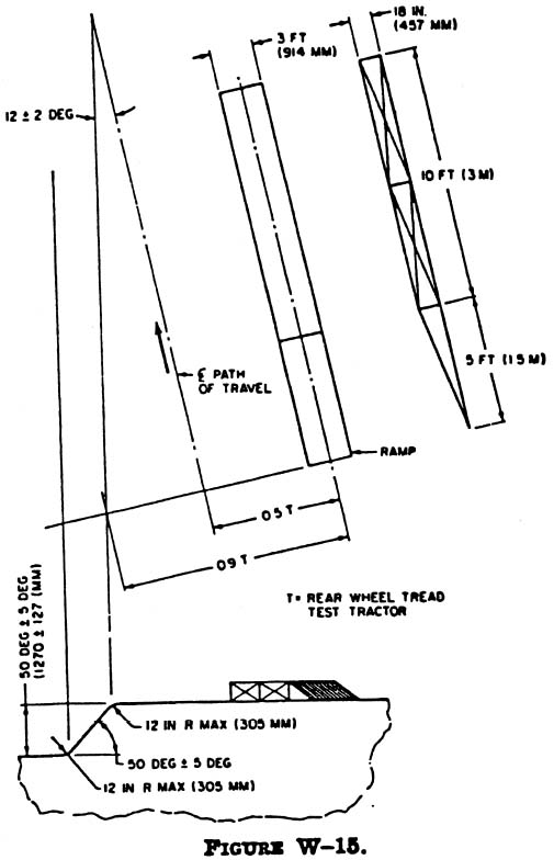
    (i) The test shall be conducted on a dry, firm soil bank as
illustrated in Figure W-15. The soil in the impact area shall have an
average cone index in the 0-in. to 6-in. (0-mm to 153-mm) layer not
less than 150 according to American Society of Agricultural Engineers
(``ASAE'') recommendation ASAE R313.1-1971 (``Soil cone penetrometer''),
as reconfirmed in 1975, which is incorporated by reference. The
incorporation by reference was approved by the Director of the Federal
Register in accordance with 5 U.S.C. 552(a) and 1 CFR part 51. The path
of vehicle travel shall be 12[deg] 2[deg] to the top edge of the bank.
    (ii) ASAE recommendation ASAE R313.1-1971, as reconfirmed in 1975,
appears in the 1977 Agricultural Engineers Yearbook, or it may be
examined at: any OSHA Regional Office; the OSHA Docket Office, U.S.
Department of Labor, 200 Constitution Avenue, NW., Room N-2625,
Washington, DC 20210 (telephone: (202) 693-2350 (TTY number: (877) 889-
5627)); or the National Archives and Records Administration (``NARA'').
(For information on the availability of this material at NARA,
telephone (202) 741-6030 or access the NARA Web site at
http://www.archives.gov/federal_register/code_of_federal_regulations/ibr_locations.html).
Copies may be purchased from the American Society of Agricultural Engineers
2950 Niles Road, St. Joseph, MI 49085.
    (5) The upper edge of the bank shall be equipped with an 18-in.
(457-mm) high ramp as described in Figure W-15 to assist in tipping the
vehicle.
    (6) The front and rear wheel-tread settings, when adjustable, shall
be at the position nearest to halfway between the minimum and maximum
settings obtainable on the vehicle. When only two settings are
obtainable, the minimum setting shall be used.
    (7) Vehicle overturn test--sideways and rearward. (i) The tractor
shall be driven under its own power along the specified path of travel
at a minimum speed of 10 mph (16 kph), or maximum vehicle speed when
under 10 mph (16 kph), up the ramp as described in paragraph (d)(5) of
this section to induce sideways overturn.
    (ii) Rear upset shall be induced by engine power with the tractor
operating in gear to obtain 3 to 5 mph (4.8 to 8 kph) at maximum
governed engine rpm, preferably by driving forward directly up a
minimum slope of two vertical to one horizontal. The engine clutch may
be used to aid in inducing the upset.
    (f) Other test procedures. When the field-upset test is not used to
determine ROPS performance, either the static test or the dynamic test,
contained in paragraph (g) or (h) of this section, shall be made.
    (g) Static test. (1) Test conditions. (i) The laboratory mounting
base shall include that part of the tractor chassis to which the
protective frame is attached, including the mounting parts.
    (ii) The protective frame shall be instrumented with the necessary
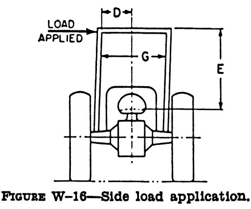
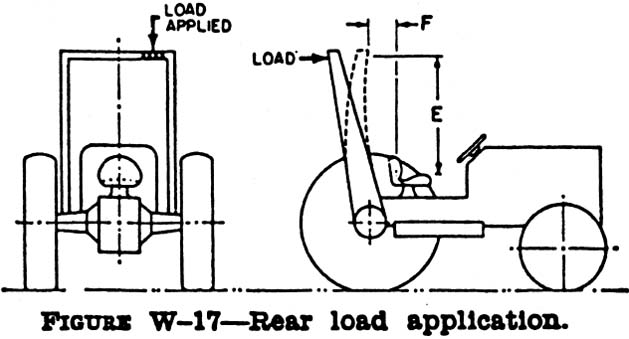
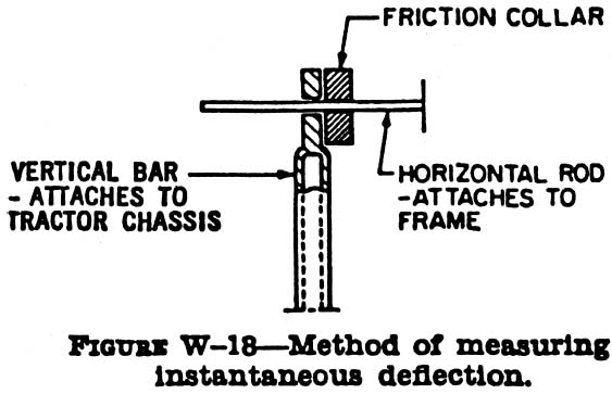
equipment to obtain the required load-deflection data at the locations
and directions specified in Figures W-16, W-17, and W-18.
    (iii) The protective frame and mounting connections shall be
instrumented with the necessary recording equipment to obtain the
required load-deflection data to be used in calculating FSB (see
paragraph (j)(3) of this section). The gauges shall be placed on
mounting connections before the installation load is applied.
    (2) Test procedure. (i) The side-load application shall be at the
upper extremity of the frame upright at a 90[deg] angle to the
centerline of the vehicle. The side load L shall be applied according
to Figure W-16. L and D shall be recorded simultaneously. The test
shall be stopped when:
    (A) The strain energy absorbed by the frame is equal to the
required input energy (Eis);
    (B) Deflection of the frame exceeds the allowable deflection; or
    (C) The frame load limit occurs before the allowable deflection is
reached in the side load.
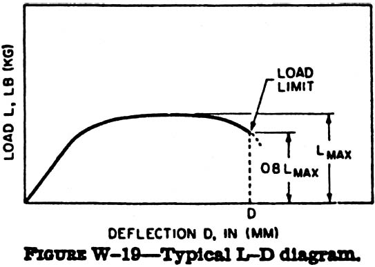
    (ii) The L-D diagram (see Figure W-19 for an example) shall be
constructed using the data obtained according to paragraph (g)(2)(i) of
this section.
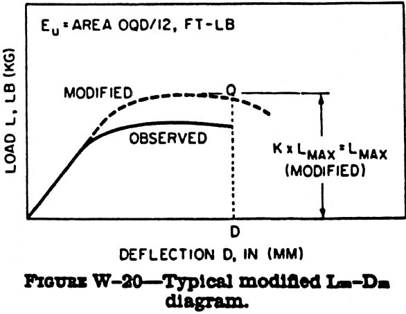
    (iii) The modified Lm-Dm diagram shall be constructed according to
paragraph (g)(2)(ii) and Figure W-20 of this section. The strain energy
absorbed by the frame (Eu) shall then be determined.
    (iv) Eis, FER, and FSB shall be calculated.
    (v) The test procedure shall be repeated on the same frame using L
(rear input; see Figure W-18) and Eir. Rear-load application shall be
distributed uniformly along a maximum projected dimension of 27 in.
(686 mm) and a maximum area of 160 sq. in. (1,032 sq. cm) normal to the
direction of load application. The load shall be applied to the upper
extremity of the frame at the point that is midway between the
centerline of the seat and the inside of the frame upright.
    (h) Dynamic test. (1) Test conditions. (i) The protective frame and
tractor shall meet the requirements of paragraphs (e)(2) or (3) of this
section, as appropriate.
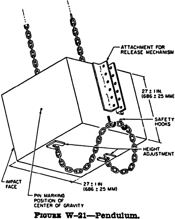
    (ii) The dynamic loading shall be produced by using a 4,410-lb
(2,000-kg) weight acting as a pendulum. The impact face of the weight
shall be 27  1 in. by 27  1 in. (686  25 mm by 686  25 mm), and shall be constructed so
that its center of gravity is within 1.0 in. (25.4 mm) of its geometric
center. The weight shall be suspended from a pivot point 18 to 22 ft
(5.5 to 6.7 m) above the point of impact on the frame, and shall be
conveniently and safely adjustable for height (see Figure W-21).
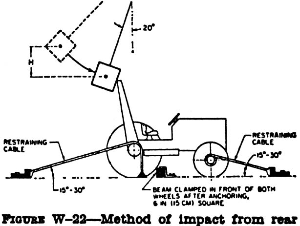
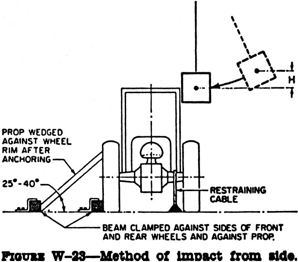
    (iii) For each phase of testing, the tractor shall be restrained
from moving when the dynamic load is applied. The restraining members
shall be 0.50- to 0.63-in. (12.5- to 16.0-mm) steel cable, and points
for attaching restraining members shall be located an appropriate
distance behind the rear axle and in front of the front axle to provide
a 15[deg] to 30[deg] angle between the restraining cable and the
horizontal. The restraining cables shall either be in the plane in
which the center of gravity of the pendulum will swing, or more than
one restraining cable shall give a resultant force in this plane (see
Figure W-22).
    (iv) The wheel-tread setting shall comply with the requirements of
paragraph (e)(6) of this section. The tires shall have no liquid
ballast, and shall be inflated to the maximum operating pressure
recommended by the tire manufacturer. With the specified tire
inflation, the restraining cables shall be tightened to provide tire
deflection of 6 to 8 percent of the nominal tire-section width. After
the vehicle is restrained properly, a wooden beam that is 6-in. x 6-in.
(150 mm x 150 mm) shall be driven tightly against the appropriate
wheels and clamped. For the test to the side, an additional wooden beam
shall be placed as a prop against the wheel nearest to the operator's
station, and shall be secured to the floor so that when it is
positioned against the wheel rim, it is at an angle of 25[deg] to
40[deg] to the horizontal. It shall have a length 20 to 25 times its
depth, and a width two to three times its depth (see Figures W-22 and
W-23).
    (v) Means shall be provided for indicating the maximum
instantaneous deflection along the line f impact. A simple friction
device is illustrated in Figure W-23.
    (vi) No repair or adjustments may be carried out during the test.
    (vii) When any cables, props, or blocking shift or break during the
test, the test shall be repeated.
    (2) Test procedure. (i) General. The frame shall be evaluated by
imposing dynamic loading to the rear, followed by a load to the side on
the same frame. The pendulum dropped from the height (see the
definition of ``H'' in paragraph (j)(3) of this section) imposes the
dynamic load. The position of the pendulum shall be so selected that
the initial point of impact on the frame shall be in line with the arc
of travel of the center of gravity of the pendulum. A quick-release
mechanism should be used but, when used, it shall not influence the
attitude of the block.
    (ii) Impact at rear. The tractor shall be restrained properly
according to paragraphs (h)(1)(iii) and (h)(1)(iv) of this section. The
tractor shall be positioned with respect to the pivot point of the
pendulum so that the pendulum is 20[deg] from the vertical prior to
impact as shown in Figure W-22. The impact shall be applied to the
upper extremity of the frame at the point that is midway between the
centerline of the frame and the inside of the frame upright of a new
frame.
    (iii) Impact at side. The blocking and restraining shall conform to
paragraphs (h)(1)(iii) and (h)(1)(iv) of this section. The center point
of impact shall be that structural member of the protective frame
likely to hit the ground first in a sideways accidental upset. The side
impact shall be applied to the side opposite that used for rear impact.
    (i) Performance requirements. (1) General. (i) The frame, overhead
weather shield, fenders, or other parts in the operator area may be
deformed in these tests, but shall not shatter or leave sharp edges
exposed to the operator, or violate the dimensions shown in Figures W-
16 and W-17, and specified as follows:

D = 2 in. (51 mm) inside of the frame upright to the vertical
centerline of the seat;
E = 30 in. (762 mm);
F = Not less than 0 in. (0 mm) and not more than 12 in. (305 mm),
measured at the centerline of the seat backrest to the crossbar along
the line of load application as shown in Figure W-17; and
G = 24 in. (610 mm).

    (ii) The material and design combination used in the protective
structure must be such that the structure can meet all prescribed
performance tests at 0 [deg]F (-18 [deg]C) according to 29 CFR
1926.1001(f)(2)(iv).
    (2) Vehicle overturn performance requirements. The requirements of
this paragraph (i) must be met in both side and rear overturns.
    (3) Static test performance requirements. Design factors shall be
incorporated in each design to withstand an overturn test as specified
by this paragraph (i). The structural requirements will be met
generally when FER is greater than 1.0 and FSB is greater than K-1 in
both side and rear loadings.
    (4) Dynamic test performance requirements. Design factors shall be
incorporated in each design to withstand the overturn test specified by
this paragraph (i). The structural requirements will be met generally
when the dimensions in this paragraph (i) are used during both side and
rear loads.
    (j) Definitions applicable to this section. (1) ``Agricultural
tractor'' means a wheel-type vehicle of more than 20 engine horsepower,
used in construction work, that is designed to furnish the power to
pull, propel, or drive implements. (SAE standard J333a-1970 (``Operator
protection for wheel-type agricultural and industrial tractors'')
defines ``agricultural tractor'' as a ``wheel-type vehicle of more than
20 engine horsepower designed to furnish the power to pull, carry,
propel, or drive implements that are designed for agricultural usage.''
Since this part 1926 applies only to construction work, the SAE
definition of ``agricultural tractor'' is adopted for purposes of this
subpart.)
    (2) ``Industrial tractor'' means that class of wheel-type tractors
of more than 20 engine horsepower (other than rubber-tired loaders and
dozers described in 29 CFR 1926.1001), used in operations such as
landscaping, construction services, loading, digging, grounds keeping,
and highway maintenance.
    (3) The following symbols, terms, and explanations apply to this
section:

E is = Energy input to be absorbed during side loading in
ft-lb (E'is in J [joules]);
E is = 723 + 0.4 W ft-lb (E' is = 100 + 0.12 W' ,
J);
E ir = Energy input to be absorbed during rear loading in
ft-lb (E' ir in J);
E ir = 0.47 W ft-lb (E' ir = 0.14 W', J);
W = Tractor weight as specified by 29 CFR 1926.1002(e)(1) and (e)(3),
in lb (W' , kg);
L = Static load, lb (kg);
D = Deflection under L, in. (mm);
L-D = Static load-deflection diagram;
Lm-Dm = Modified static load-deflection diagram
(Figure W-20). To account for an increase in strength due to an
increase in strain rate, raise L in the plastic range L x K;
K = Increase in yield strength induced by higher rate of loading (1.3
for hot, rolled, low-carbon steel 1010-1030). Low carbon is preferable;
however, when higher carbon or other material is used, K must be
determined in the laboratory. Refer to Norris, C.H., Hansen, R.J.,
Holley, M.J., Biggs, J.M., Namyet, S., and Minami, J.V., Structural
Design for Dynamic Loads, McGraw-Hill, New York, 1959, p. 3;
Lmax = Maximum observed static load;
Load Limit = Point on a continuous L-D curve at which the observed
static load is 0.8 Lmax (refer to Figure W-19);
Eu = Strain energy absorbed by the frame, ft-lb (J); area
under the Lm-Dm curve;
FER = Factor of energy ratio, FER = EuEis; also,
FER = EuEir;
Pb = Maximum observed force in mounting connection under a
static load, L, lb (kg);
Pu = Ultimate force capacity of mounting connection, lb
(kg);
FSB = Design margin for a mounting connection
(PuPb)-1; and
H = Vertical height of lift of 4,410-lb (2,000-kg) weight, in. (H',
mm). The weight shall be pulled back so that the height of its center
of gravity above the point of impact is defined as follows: H = 4.92 +
0.00190 W (H' = 125 + 0.107 W') (see Figure W-24).

    (k) Source of standard. The standard in this section is derived
from, and restates, in part, Society of Automotive Engineers (``SAE'')
standard J334a-1970 (``Protective frame test procedures and performance
requirements''). The SAE standard appears in the 1971 SAE Handbook,
which may be examined at any OSHA regional office.

Sec.  1926.1003  Overhead protection for operators of agricultural and
industrial tractors used in construction.

    (a) General. (1) Purpose. When overhead protection is provided on
wheel-type agricultural and industrial tractors, the overhead
protection shall be designed and installed according to the
requirements contained in this section. The provisions of 29 CFR
1926.1001 for rubber-tired dozers and rubber-tired loaders may be used
instead of the standards contained in this section. The purpose of this
standard is to minimize the possibility of operator injury resulting
from overhead hazards such as flying and falling objects, and at the
same time to minimize the possibility of operator injury from the cover
itself in the event of accidental upset.
    (2) Applicability. This standard applies to wheel-type agricultural
and industrial tractors used in construction work (see 29 CFR
1926.1002(b) and (j)). In the case of machines to which 29 CFR 1926.604
(relating to site clearing) also applies, the overhead protection may
be either the type of protection provided in 29 CFR 1926.604, or the
type of protection provided by this section.
    (b) Overhead protection. When overhead protection is installed on
wheel-type agricultural or industrial tractors used in construction
work, it shall meet the requirements of this paragraph. The overhead
protection may be constructed of a solid material. When grid or mesh is
used, the largest permissible opening shall be such that the maximum circle
that can be inscribed between the elements of the grid or mesh is 1.5 in.
(38 mm) in diameter. The overhead protection shall not be installed in such
a way as to become a hazard in the case of upset.
    (c) Test procedures--general. (1) The requirements of 29 CFR
1926.1002(d), (e), and (f) shall be met.
    (2) Static and dynamic rear load application shall be distributed
uniformly along a maximum projected dimension of 27 in. (686 mm), and a
maximum area of 160 sq. in. (1,032 sq. cm), normal to the direction of
load application. The load shall be applied to the upper extremity of
the frame at the point that is midway between the centerline of the
seat and the inside of the frame upright.
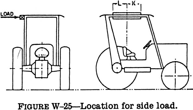
    (3) The static and dynamic side load application shall be
distributed uniformly along a maximum projected dimension of 27 in.
(686 mm), and a maximum area of 160 sq. in. (1,032 sq. cm), normal to
the direction of load application. The direction of load application is
the same as in 29 CFR 1926.1002 (g) and (h). To simulate the
characteristics of the structure during an upset, the center of load
application may be located from a point 24 in. (610 mm) (K) forward to
12 in. (305 mm) (L) rearward of the front of the seat backrest, to best
use the structural strength (see Figure W-25).
    (d) Drop test procedures. (1) The same frame shall be subjected to
the drop test following either the static or dynamic test.
    (2) A solid steel sphere or material of equivalent spherical
dimension weighing 100 lb (45.4 kg) shall be dropped once from a height
10 ft (3.08 m) above the overhead cover.
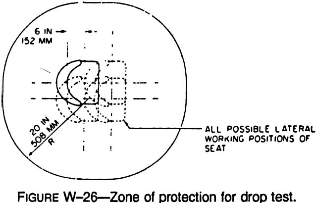
    (3) The point of impact shall be on the overhead cover at a point
within the zone of protection as shown in Figure W-26, which is
furthest removed from major structural members.
    (e) Crush test procedure. (1) The same frame shall be subjected to
the crush test following the drop test and static or dynamic test.
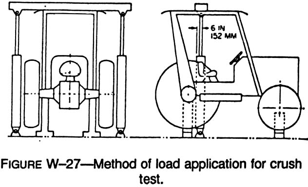
    (2) The test load shall be applied as shown in Figure W-27, with
the seat positioned as specified in 29 CFR 1926.1002(d)(4). Loading
cylinders shall be mounted pivotally at both ends. Loads applied by
each cylinder shall be equal within two percent, and the sum of the
loads of the two cylinders shall be two times the tractor weight as set
forth in 29 CFR 1926.1002(e)(1). The maximum width of the beam
illustrated in Figure W-27 shall be 6 in. (152 mm).
    (f) Performance requirements. (1) General. The performance
requirements set forth in 29 CFR 1926.1002(i)(2), (3), and (4) shall be
met.
    (2) Drop test performance requirements. (i) Instantaneous
deformation due to impact of the sphere shall not enter the protected
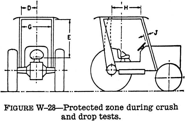
zone as illustrated in Figures W-25, W-26, and W-28.
    (ii) In addition to the dimensions set forth in 29 CFR
1926.1002(i)(1)(i), the following dimensions apply to Figure W-28:

H = 17.5 in. (444 mm); and
J = 2 in. (50.8 mm), measured from the outer periphery of the steering
wheel.

    (3) Crush test performance requirements. The protected zone as
described in Figure W-28 must not be violated.
    (g) Source of standard. This standard is derived from, and
restates, in part, the portions of Society of Automotive Engineers
(``SAE'') standard J167-1970 (``Protective frame with overhead
protection--test procedures and performance requirements''), which
pertain to overhead protection requirements. The SAE standard appears
in the 1971 SAE Handbook, which may be examined at any OSHA regional
office.

Appendix A to Subpart W--Figures W-14 through W-28

BILLING CODE 4510-26-P


PART 1928--[AMENDED]

Subpart C--[Amended]

0
3. Revise the authority citation to part 1928 to read as follows:

    Authority: Sections 4, 6, and 8 of the Occupational Safety and
Health Act of 1970 (29 U.S.C. 653, 655, 657); and Secretary of
Labor's Order No. 12-71 (36 FR 8754), 8-76 (41 FR 25059), 9-83 (48
FR 35736), 1-90 (55 FR 9033), 6-96 (62 FR 111), 3-2000 (65 FR 50017)
or 5-2002 (67 FR 65008) as applicable; and 29 CFR part 1911.
    Section 1928.21 also issued under section 29, Hazardous
Materials Transportation Uniform Safety Act of 1990 (Pub. L. 101-
615, 104 Stat. 3244 (49 U.S.C. 1801-1819 and 5 U.S.C. 553)).


0
4. Revise paragraph (b)(1) of Sec.  1928.51 to read as follows:


Sec.  1928.51  Roll-over protective structures (ROPS) for tractors used
in agricultural operations.

* * * * *
    (b) * * *
    (1) Roll-over protective structures (ROPS). ROPS shall be provided
by the employer for each tractor operated by an employee. Except as
provided in paragraph (b)(5) of this section, a ROPS used on wheel-type
tractors shall meet the test and performance requirements of 29 CFR
1928.52, 1928.53, or 1926.1002 as appropriate. A ROPS used on track-
type tractors shall meet the test and performance requirements of 29
CFR 1926.1001.
* * * * *

0
5. Add Sec. Sec.  1928.52, 1928.53, and a new Appendix B to subpart C
to read as follows:


Sec.  1928.52  Protective frames for wheel-type agricultural tractors--
test procedures and performance requirements.

    (a) Purpose. The purpose of this section is to establish the test
and performance requirements for a protective frame designed for wheel-
type agricultural tractors to minimize the frequency and severity of
operator injury resulting from accidental upsets. General requirements
for the protection of operators are specified in 29 CFR 1928.51.
    (b) Types of tests. All protective frames for wheel-type
agricultural tractors shall be of a model that has been tested as
follows:
    (1) Laboratory test. A laboratory energy-absorption test, either
static or dynamic, under repeatable and controlled loading, to permit
analysis of the protective frame for compliance with the performance
requirements of this standard.
    (2) Field-upset test. A field-upset test under controlled
conditions, both to the side and rear, to verify the effectiveness of
the protective system under actual dynamic conditions. Such testing may
be omitted when:
    (i) The analysis of the protective-frame static-energy absorption
test results indicates that both FERis and FERir
(as defined in paragraph (d)(2)(ii) of this section) exceed 1.15; or
    (ii) The analysis of the protective-frame dynamic-energy absorption
test results indicates that the frame can withstand an impact of 15
percent greater than the impact it is required to withstand for the
tractor weight as shown in Figure C-7.
    (c) Descriptions. (1) Protective frame. A protective frame is a
structure comprised of uprights mounted to the tractor, extending above
the operator's seat. A typical two-post frame is shown in Figure C-1.
    (2) Overhead weather shield. When an overhead weather shield is
available for attachment to the protective frame, it may be in place
during tests provided it does not contribute to the strength of the
protective frame.
    (3) Overhead falling object protection. When an overhead falling-
object protection device is available for attachment to the protective
frame, it may be in place during tests provided it does not contribute
to the strength of the protective frame.
    (d) Test procedures. (1) General. (i) The tractor weight used shall
be that of the heaviest tractor model on which the protective frame is
to be used.
    (ii) Each test required under this section shall be performed on a
new protective frame. Mounting connections of the same design shall be
used during each such test.
    (iii) Instantaneous deflection shall be measured and recorded for
each segment of the test; see paragraph (e)(1)(i) of this section for
permissible deflections.
    (iv) The seat-reference point (``SRP'') in Figure C-3 is that point
where the vertical line that is tangent to the most forward point at
the longitudinal seat centerline of the seat back, and the horizontal
line that is tangent to the highest point of the seat cushion,
intersect in the longitudinal seat section. The seat-reference point
shall be determined with the seat unloaded and adjusted to the highest
and most rearward position provided for seated operation of the
tractor.
    (v) When the centerline of the seat is off the longitudinal center,
the frame loading shall be on the side with the least space between the
centerline of seat and the protective frame.
    (vi) Low-temperature characteristics of the protective frame or its
material shall be demonstrated as specified in paragraph (e)(1)(ii) of
this section.
    (vii) Rear input energy tests (static, dynamic, or field-upset)
need not be performed on frames mounted to tractors having four driven
wheels and more than one-half their unballasted weight on the front
wheels.
    (viii) Accuracy table:

------------------------------------------------------------------------
            Measurements                           Accuracy
------------------------------------------------------------------------
Deflection of the frame, in. (mm)..  5 percent of the
                                      deflection measured.
Vertical weight, lb (kg)...........  5 percent of the weight
                                      measured.
Force applied to the frame, pounds   5 percent of the force
 force (newtons).                     measured.
Dimensions of the critical zone,     0.5 in. (12.5 mm).
 in. (mm).
------------------------------------------------------------------------

    (2) Static test procedure. (i) The following test conditions shall
be met:
    (A) The laboratory mounting base shall be the tractor chassis for
which the protective frame is designed, or its equivalent;
    (B) The protective frame shall be instrumented with the necessary
equipment to obtain the required load-deflection data at the locations
and directions specified in Figures C-2 and C-3; and
    (C) When the protective frame is of a one- or two-upright design,
mounting connections shall be instrumented with the necessary equipment
to record the required force to be used in paragraph (d)(2)(iii)(E) and
(J) of this section. Instrumentation shall be placed on mounting
connections before installation load is applied.
    (ii) The following definitions shall apply:

W = Tractor weight (see 29 CFR 1928.51(a)) in lb (W' in kg);
Eis = Energy input to be absorbed during side loading in ft-lb (E'is in
J [joules]);
Eis = 723 + 0.4 W (E'is = 100 + 0.12 W');
Eir = Energy input to be absorbed during rear loading in ft-lb (E'ir in
J);
Eir = 0.47 W (E'ir = 0.14 W');
L = Static load, lbf [pounds force], (N) [newtons];
D = Deflection under L, in. (mm);
L-D = Static load-deflection diagram;
Lmax = Maximum observed static load;
Load Limit = Point on a continuous L-D curve where the observed static
load is 0.8 Lmax on the down slope of the curve (see Figure C-5);
Eu = Strain energy absorbed by the frame in ft-lb (J); area under the
L-D curve;
FER = Factor of energy ratio;
FERis = EuEis;
FERir = EuEir;
Pb = Maximum observed force in mounting connection under a static load,
L lbf (N);
Pu = Ultimate force capacity of a mounting connection, lbf (N);
FSB = Design margin for a mounting connection; and
FSB = Pu/Pb

    (iii) The test procedures shall be as follows:
    (A) Apply the rear load according to Figure C-3, and record L and D
simultaneously. Rear-load application shall be distributed uniformly on
the frame over an area perpendicular to the direction of load
application, no greater than 160 sq. in. (1,032 sq. cm) in size, with
the largest dimension no greater than 27 in. (686 mm). The load shall
be applied to the upper extremity of the frame at the point that is
midway between the center of the frame and the inside of the frame upright.
When no structural cross member exists at the rear of the frame, a substitute
test beam that does not add strength to the frame may be used to complete
this test procedure. The test shall be stopped when:
    (1) The strain energy absorbed by the frame is equal to or greater
than the required input energy Eir; or
    (2) Deflection of the frame exceeds the allowable deflection (see
paragraph (e)(1)(i) of this section); or
    (3) Frame load limit occurs before the allowable deflection is
reached in rear load (see Figure C-5).
    (B) Using data obtained under paragraph (d)(2)(iii)(A) of this
section, construct the L-D diagram shown in Figure C-5;
    (C) Calculate Eir;
    (D) Calculate FERir;
    (E) Calculate FSB as required by paragraph (d)(2)(i)(C) of this
section;
    (F) Apply the side-load tests on the same frame, and record L and D
simultaneously. Side-load application shall be at the upper extremity
of the frame at a 90[deg] angle to the centerline of the vehicle. The
side load shall be applied to the longitudinal side farthest from the
point of rear-load application. Apply side load L as shown in Figure C-
2. The test shall be stopped when:
    (1) The strain energy absorbed by the frame is equal to or greater
than the required input energy Eis; or
    (2) Deflection of the frame exceeds the allowable deflection (see
paragraph (e)(1)(i) of this section); or
    (3) Frame load limit occurs before the allowable deflection is
reached in side load (see Figure C-5).
    (G) Using data obtained in paragraph (d)(2)(iii)(F) of this
section, construct the L-D diagram as shown in Figure C-5;
    (H) Calculate Eis;
    (I) Calculate FERis; and
    (J) Calculate FSB as required by paragraph (d)(2)(i)(C) of this
section.
    (3) Dynamic test procedure. (i) The following test conditions shall
be met:
    (A) The protective frame and tractor shall be tested at the weight
defined by 29 CFR 1928.51(a);
    (B) The dynamic loading shall be accomplished by using a 4,410-lb
(2,000-kg) weight acting as a pendulum. The impact face of the weight
shall be 27  1 in. by 27  1 in. (686  25 mm by 686  25 mm), and shall be constructed so
that its center of gravity is within 1.0 in. (25.4 mm) of its geometric
center. The weight shall be suspended from a pivot point 18 to 22 ft
(5.5 to 6.7 m) above the point of impact on the frame, and shall be
conveniently and safely adjustable for height (see Figure C-6);
    (C) For each phase of testing, the tractor shall be restrained from
moving when the dynamic load is applied. The restraining members shall
have strength no less than, and elasticity no greater than, that of
0.50-in. (12.7-mm) steel cable. Points of attachment for the
restraining members shall be located an appropriate distance behind the
rear axle and in front of the front axle to provide a 15[deg] to
30[deg] angle between a restraining cable and the horizontal. For
impact from the rear, the restraining cables shall be located in the
plane in which the center of gravity of the pendulum will swing, or
alternatively, two sets of symmetrically located cables may be used at
lateral locations on the tractor. For impact from the side, restraining
cables shall be used as shown in Figures C-8 and C-9;
    (D) The front and rear wheel-tread settings, when adjustable, shall
be at the position nearest to halfway between the minimum and maximum
settings obtainable on the vehicle. When only two settings are
obtainable, the minimum setting shall be used. The tires shall have no
liquid ballast, and shall be inflated to the maximum operating pressure
recommended by the manufacturer. With the specified tire inflation, the
restraining cable shall be tightened to provide tire deflection of 6 to
8 percent of the nominal tire-section width. After the vehicle is
restrained properly, a wooden beam no less than 6-in. x 6-in. (150-mm x
150-mm) in cross section shall be driven tightly against the
appropriate wheels and clamped. For the test to the side, an additional
wooden beam shall be placed as a prop against the wheel nearest to the
operator's station, and shall be secured to the base so that it is held
tightly against the wheel rim during impact. The length of this beam
shall be chosen so that it is at an angle of 25[deg] to 40[deg] to the
horizontal when it is positioned against the wheel rim. It shall have a
length 20 to 25 times its depth, and a width two to three times its
depth (see Figures C-8 and C-9);
    (E) Means shall be provided for indicating the maximum
instantaneous deflection along the line of impact. A simple friction
device is illustrated in Figure C-4;
    (F) No repairs or adjustments shall be made during the test; and
    (G) When any cables, props, or blocking shift or break during the
test, the test shall be repeated.
    (ii) H = Vertical height of the center of gravity of a 4,410-lb
(2,000-kg) weight in in. (H' in mm). The weight shall be pulled back so
that the height of its center of gravity above the point of impact is:
H = 4.92 + 0.00190 W (H' = 125  0.170 W') (see Figure C-7).
    (iii) The test procedures shall be as follows:
    (A) The frame shall be evaluated by imposing dynamic loading from
the rear, followed by a load to the side on the same frame. The
pendulum swinging from the height determined by paragraph (d)(3)(ii) of
this section shall be used to impose the dynamic load. The position of
the pendulum shall be so selected that the initial point of impact on
the frame is in line with the arc of travel of the center of gravity of
the pendulum. When a quick-release mechanism is used, it shall not
influence the attitude of the block;
    (B) Impact at rear. The tractor shall be restrained properly
according to paragraphs (d)(3)(i)(C) and (d)(3)(i)(D) of this section.
The tractor shall be positioned with respect to the pivot point of the
pendulum so that the pendulum is 20[deg] from the vertical prior to
impact as shown in Figure C-8. The impact shall be applied to the upper
extremity of the frame at the point that is midway between the
centerline of the frame and the inside of the frame upright. When no
structural cross member exists at the rear of the frame, a substitute
test beam that does not add to the strength of the frame may be used to
complete the test procedure; and
    (C) Impact at side. The blocking and restraining shall conform to
paragraphs (d)(3)(i)(C) and (d)(3)(i)(D) of this section. The center
point of impact shall be at the upper extremity of the frame at a point
most likely to hit the ground first, and at a 90[deg] to the centerline
of the vehicle (see Figure C-9). The side impact shall be applied to
the longitudinal side farthest from the point of rear impact.
    (4) Field-upset test procedure. (i) The following test conditions
shall be met:
    (A) The tractor shall be tested at the weight defined in 29 CFR
1928.51(a);
    (B) The following provisions address soil bank test conditions.
    (1) The test shall be conducted on a dry, firm soil bank. The soil
in the impact area shall have an average cone index in the 0-in. to 6-
in. (0-mm to 152-mm) layer of not less than 150. Cone index shall be
determined according to American Society of Agricultural Engineers
(``ASAE'') recommendation ASAE R313.1-1971 (``Soil cone
penetrometer''), as reconfirmed in 1975, which is incorporated by
reference. The incorporation by reference was approved by the Director
of the Federal Register in accordance with 5 U.S.C. 552(a) and 1 CFR
part 51. The path of vehicle travel shall be 12[deg]
2[deg] to the top edge of the bank.
    (2) ASAE recommendation R313.1-1971, as reconfirmed in 1975,
appears in the 1977 Agricultural Engineers Yearbook, or it may be
examined at: Any OSHA Regional Office; the OSHA Docket Office, U.S.
Department of Labor, 200 Constitution Avenue, NW., Room N-2625,
Washington, DC 20210 (telephone: (202) 693-2350 (TTY number: (877) 889-
5627)); or the National Archives and Records Administration (``NARA'').
(For information on the availability of this material at NARA,
telephone (202) 741-6030 or access the NARA Web site at
http://www.archives.gov/federal_register/code_of_federal_regulations/ibr_locations.html.)
Copies may be purchased from the American Society of Agricultural Engineers,
2950 Niles Road, St. Joseph, MI 49085.
    (C) An 18-in. (457-mm) high ramp (see Figure C-10) shall be used to
assist in upsetting the vehicle to the side; and
    (D) The front and rear wheel-tread settings, when adjustable, shall
be at the position nearest to halfway between the minimum and maximum
settings obtainable on the vehicle. When only two settings are
obtainable, the minimum setting shall be used.
    (ii) Field upsets shall be induced to the rear and side as follows:
    (A) Rear upset shall be induced by engine power, with the tractor
operating in gear to obtain 3 to 5 mph (4.8 to 8.0 kph) at maximum
governed engine rpm by driving forward directly up a minimum slope of
60[deg]  5[deg] as shown in Figure C-11, or by an
alternative equivalent means. The engine clutch may be used to aid in
inducing the upset; and
    (B) To induce side upset, the tractor shall be driven under its own
power along the specified path of travel at a minimum speed of 10 mph
(16 kph), or at maximum vehicle speed when under 10 mph (16 kph), and
over the ramp as described in paragraph (d)(4)(i)(C) of this section.
    (e) Performance requirements. (1) General requirements. (i) The
frame, overhead weather shield, fenders, or other parts in the operator
area may be deformed in these tests, but shall not shatter or leave
sharp edges exposed to the operator, or encroach on the dimensions
shown in Figures C-2 and C-3, and specified as follows:

d = 2 in. (51 mm) inside of the frame upright to the vertical
centerline of the seat;
e = 30 in. (762 mm) at the longitudinal centerline;
f = Not greater than 4 in. (102 mm) to the rear edge of the crossbar,
measured forward of the seat-reference point (``SRP'');
g = 24 in. (610 mm) minimum; and
m = Not greater than 12 in. (305 mm), measured from the seat-reference
point to the forward edge of the crossbar.

    (ii) The protective structure and connecting fasteners must pass
the static or dynamic tests described in paragraphs (d)(2), (d)(3), or
(d)(4) of this section at a metal temperature of 0 [deg]F (-18 [deg]C)
or below, or exhibit Charpy V-notch impact strengths as follows:

10-mm x 10-mm (0.394-in. x 0.394-in.) specimen: 8.0 ft-lb (10.8 J) at -
20 [deg]F (-30 [deg]C);
10-mm x 7.5-mm (0.394-in. x 0.296-in.) specimen: 7.0 ft-lb (9.5 J) at -
20 [deg]F (-30 [deg]C);
10-mm x 5-mm (0.394-in. x 0.197-in.) specimen: 5.5 ft-lb (7.5 J) at -20
[deg]F (-30 [deg]C); or
10-mm x 2.5-mm (0.394-in. x 0.098-in.) specimen: 4.0 ft-lb (5.5 J) at -
20 [deg]F (-30 [deg]C).


Specimens shall be longitudinal and taken from flat stock, tubular, or
structural sections before forming or welding for use in the frame.
Specimens from tubular or structural sections shall be taken from the
middle of the side of greatest dimension, not to include welds.
    (2) Static test-performance requirements. In addition to meeting
the requirements of paragraph (e)(1) of this section for both side and
rear loads, FERis and FERir, shall be greater than 1.0, and when the
ROPS contains one or two upright frames only, FSB shall be greater than
1.3.
    (3) Dynamic test-performance requirements. The structural
requirements shall be met when the dimensions in paragraph (e)(1) of
this section are used in both side and rear loads.
    (4) Field-upset test performance requirements. The requirements of
paragraph (e)(1) of this section shall be met for both side and rear
upsets.


Sec.  1928.53  Protective enclosures for wheel-type agricultural
tractors--test procedures and performance requirements.

    (a) Purpose. The purpose of this section is to establish the test
and performance requirements for a protective enclosure designed for
wheel-type agricultural tractors to minimize the frequency and severity
of operator injury resulting from accidental upset. General
requirements for the protection of operators are specified in 29 CFR
1928.51.
    (b) Types of tests. All protective enclosures for wheel-type
agricultural tractors shall be of a model that has been tested as
follows:
    (1) Laboratory test. A laboratory energy-absorption test, either
static or dynamic, under repeatable and controlled loading, to permit
analysis of the protective enclosure for compliance with the
performance requirements of this standard; and
    (2) Field-upset test. A field-upset test under controlled
conditions, both to the side and rear, to verify the effectiveness of
the protective system under actual dynamic conditions. This test may be
omitted when:
    (i) The analysis of the protective-frame static-energy absorption
test results indicates that both FERis and FERir (as defined in
paragraph (d)(2)(ii) of this section) exceed 1.15; or
    (ii) The analysis of the protective-frame dynamic-energy absorption
test results indicates that the frame can withstand an impact 15
percent greater than the impact it is required to withstand for the
tractor weight as shown in Figure C-7.
    (c) Description. A protective enclosure is a structure comprising a
frame and/or enclosure mounted to the tractor. A typical enclosure is
shown in Figure C-12.
    (d) Test procedures. (1) General. (i) The tractor weight used shall
be that of the heaviest tractor model on which the protective enclosure
is to be used.
    (ii) Each test required under this section shall be performed on a
protective enclosure with new structural members. Mounting connections
of the same design shall be used during each test.
    (iii) Instantaneous deflection shall be measured and recorded for
each segment of the test; see paragraph (e)(1)(i) of this section for
permissible deflections.
    (iv) The seat-reference point (``SRP'') in Figure C-14 is that
point where the vertical line that is tangent to the most forward point
at the longitudinal seat centerline of the seat back, and the
horizontal line that is tangent to the highest point of the seat
cushion, intersect in the longitudinal seat section. The seat-reference
point shall be determined with the seat unloaded and adjusted to the
highest and most rearward position provided for seated operations of
the tractor.
    (v) When the centerline of the seat is off the longitudinal center,
the protective-enclosure loading shall be on the side with least space
between the centerline of the seat and the protective enclosure.
    (vi) Low-temperature characteristics of the protective enclosure or
its material shall be demonstrated as specified in paragraph (e)(1)(ii)
of this section.
    (vii) Rear input energy tests (static, dynamic, or field-upset)
need not be performed on enclosures mounted to tractors having four
driven wheels and more than one-half their unballasted weight on the
front wheels.
    (viii) Accuracy table:

------------------------------------------------------------------------
            Measurements                           Accuracy
------------------------------------------------------------------------
Deflection of the enclosure, in.      5 percent of the
 (mm).                                deflection measured.
Vertical weight, pounds (kg).......   5 percent of the
                                      weight measured.
Force applied to the enclosure,       5 percent of the force
 pounds force (newtons).              measured.
Dimensions of the critical zone,      0.5 in. (12.5 mm).
 in. (mm).
------------------------------------------------------------------------

    (ix) When movable or normally removable portions of the enclosure
add to structural strength, they shall be placed in configurations that
contribute least to structural strength during the test.
    (2) Static test procedure. (i) The following test conditions shall
be met:
    (A) The laboratory mounting base shall be the tractor chassis for
which the protective enclosure is designed, or its equivalent; and
    (B) The protective enclosure shall be instrumented with the
necessary equipment to obtain the required load-deflection data at the
locations and directions specified in Figures C-13 and C-14.
    (ii) The following definitions shall apply:

W = Tractor weight (see 29 CFR 1928.31(a)) in lb (W' in kg);
Eis = Energy input to be absorbed during side loading in ft-lb (E'is in
J [joules]);
Eis = 723 + 0.4 W (E'is = 100 + 0.12 W');
Eir = Energy input to be absorbed during rear loading in ft-lb (E'ir in
J);
Eir = 0.47 W (E'ir = 0.14 W');
L = Static load, lbf [pounds force], (N) [newtons];
D = Deflection under L, in. (mm);
L-D = Static load-deflection diagram;
Lmax = Maximum observed static load;
Load Limit = Point on a continuous L-D curve where the observed static
load is 0.8 Lmax on the down slope of the curve (see Figure C-5);
Eu = Strain energy absorbed by the protective enclosure in ft-lbs (J);
area under the L-D curve;
FER = Factor of energy ratio;
FERis = Eu/Eis; and
FERir = Eu/Eir

    (iii) The test procedures shall be as follows:
    (A) When the protective-frame structures are not an integral part
of the enclosure, the direction and point of load application for both
side and rear shall be the same as specified in 29 CFR 1928.52(d)(2);
    (B) When the protective-frame structures are an integral part of
the enclosure, apply the rear load according to Figure C-14, and record
L and D simultaneously. Rear-load application shall be distributed
uniformly on the frame structure over an area perpendicular to the load
application, no greater than 160 sq. in. (1,032 sq. cm) in size, with
the largest dimension no greater than 27 in. (686 mm). The load shall
be applied to the upper extremity of the structure at the point that is
midway between the centerline of the protective enclosure and the
inside of the protective structure. When no structural cross member
exists at the rear of the enclosure, a substitute test beam that does
not add strength to the structure may be used to complete this test
procedure. The test shall be stopped when:
    (1) The strain energy absorbed by the structure is equal to or
greater than the required input energy Eir; or
    (2) Deflection of the structure exceeds the allowable deflection
(see paragraph (e)(1)(i) of this section); or
    (3) The structure load limit occurs before the allowable deflection
is reached in rear load (see Figure C-5);
    (C) Using data obtained in paragraph (d)(2)(iii)(B) of this
section, construct the L-D diagram for rear loads as shown in Figure C-
5;
    (D) Calculate Eir;
    (E) Calculate FERir;
    (F) When the protective-frame structures are an integral part of
the enclosure, apply the side load according to Figure C-13, and record
L and D simultaneously. Static side-load application shall be
distributed uniformly on the frame over an area perpendicular to the
direction of load application, and no greater than 160 sq. in. (1,032
sq. cm) in size, with the largest dimension no greater than 27 in. (686
mm). Side-load application shall be at a 90[deg] angle to the
centerline of the vehicle. The center of the side-load application
shall be located between point k, 24 in. (610 mm) forward of the seat-
reference point, and point l, 12 in. (305 mm) rearward of the seat-
reference point, to best use the structural strength (see Figure C-13).
This side load shall be applied to the longitudinal side farthest from
the point of rear-load application. The test shall be stopped when:
    (1) The strain energy absorbed by the structure is equal to or
greater than the required input energy Eis; or
    (2) Deflection of the structure exceeds the allowable deflection
(see paragraph (e)(1)(i) of this section); or
    (3) The structure load limit occurs before the allowable deflection
is reached in side load (see Figure C-5);
    (G) Using data obtained in paragraph (d)(2)(iii)(F) of this
section, construct the L-D diagram for the side load as shown in Figure
C-5;
    (H) Calculate FERis; and
    (I) Calculate FERir.
    (3) Dynamic test procedure. (i) The following test conditions shall
be met:
    (A) The protective enclosure and tractor shall be tested at the
weight defined by 29 CFR 1928.51(a);
    (B) The dynamic loading shall be accomplished by using a 4,410-lb
(2,000-kg) weight acting as a pendulum. The impact face of the weight
shall be 27  1 in. by 27  1 in. (686  25 mm by 686  25 mm), and shall be constructed so
that its center of gravity is within 1.0 in. (25.4 mm) of its geometric
center. The weight shall be suspended from a pivot point 18 to 22 ft
(5.5 to 6.7 m) above the point of impact on the enclosure, and shall be
conveniently and safely adjustable for height (see Figure C-6);
    (C) For each phase of testing, the tractor shall be restrained from
moving when the dynamic load is applied. The restraining members shall
have strength no less than, and elasticity no greater than, that of
0.50-in. (12.7-mm) steel cable. Points of attachment for the
restraining members shall be located an appropriate distance behind the
rear axle and in front of the front axle to provide a 15[deg] to
30[deg] angle between the restraining cable and the horizontal. For
impact from the rear, the restraining cables shall be located in the
plane in which the center of gravity of the pendulum will swing, or
alternatively, two sets of symmetrically located cables may be used at
lateral locations on the tractor. For the impact from the side,
restraining cables shall be used as shown in Figures C-15 and C-16;
    (D) The front and rear wheel-tread settings, when adjustable, shall
be at the position nearest to halfway between the minimum and maximum
settings obtainable on the vehicle. When only two settings are
obtainable, the minimum setting shall be used. The tires shall have no
liquid ballast, and shall be inflated to the maximum operating pressure
recommended by the manufacturer. With specified tire inflation, the
restraining cable shall be tightened to provide tire deflection of 6 to
8 percent of nominal tire section width. After the vehicle is retrained
properly, a wooden beam no smaller than 6-in. x 6-in. (150-mm x 150-mm)
cross-section shall be driven tightly against the appropriate wheels
and clamped. For the test to the side, an additional wooden beam shall
be placed as a prop against the wheel nearest the operator's station,
and shall be secured to the base so that it is held tightly against the
wheel rim during impact. The length of this beam shall be chosen so
that it is at an angle of 25[deg] to 40[deg] to the horizontal when it
is positioned against the wheel rim. It shall have a length 20 to 25
times its depth, and a width two to three times its depth (see Figures
C-15 and C-16);
    (E) Means shall be provided for indicating the maximum
instantaneous deflection along the line of impact. A simple friction
device is illustrated in Figure C-4;
    (F) No repair or adjustments shall be made during the test; and
    (G) When any cables, props, or blocking shift or break during the
test, the test shall be repeated.
    (ii) H = Vertical height of the center of gravity of a 4,410-lb
(2,000-kg) weight in in. (H' in mm). The weight shall be pulled back so
that the height of its center of gravity above the point of impact is:
H = 4.92 + 0.00190 W (H' = 125 + 0.107 W') (see Figure C-7).
    (iii) The test procedures shall be as follows:
    (A) The enclosure structure shall be evaluated by imposing dynamic
loading from the rear, followed by a load to the side on the same
enclosure structure. The pendulum swinging from the height determined
by paragraph (d)(3)(ii) of this section shall be used to impose the
dynamic load. The position of the pendulum shall be so selected that
the initial point of impact on the protective structure is in line with
the arc of travel of the center of gravity of the pendulum. When a
quick-release mechanism is used, it shall not influence the attitude of
the block;
    (B) Impact at rear. The tractor shall be restrained properly
according to paragraphs (d)(3)(i)(C) and (d)(3)(i)(D) of this section.
The tractor shall be positioned with respect to the pivot point of the
pendulum so that the pendulum is 20[deg] from the vertical prior to
impact as shown in Figure C-15. The impact shall be applied to the
upper extremity of the enclosure structure at the point that is midway
between the centerline of the enclosure structure and the inside of the
protective structure. When no structural cross member exists at the
rear of the enclosure structure, a substitute test beam that does not
add to the strength of the structure may be used to complete the test
procedure; and
    (C) Impact at side. The blocking and restraining shall conform to
paragraphs (d)(3)(i)(C) and (d)(3)(i)(D) of this section. The center
point of impact shall be at the upper extremity of the enclosure at a
90[deg] angle to the centerline of the vehicle, and located between a
point k, 24 in. (610 mm) forward of the seat-reference point, and a
point l, 12 in. (305 mm) rearward of the seat-reference point, to best
use the structural strength (see Figure C-13). The side impact shall be
applied to the longitudinal side farthest from the point of rear
impact.
    (4) Field-upset test procedure. (i) The following test conditions
shall be met:
    (A) The tractor shall be tested at the weight defined in 29 CFR
1928.51(a);
    (B) The following provisions address soil bank test conditions.
    (1) The test shall be conducted on a dry, firm soil bank. The soil
in the impact area shall have an average cone index in the 0-in. to 6-
in. (0-mm to 152-mm) layer of not less than 150. Cone index shall be
determined according to American Society of Agricultural Engineers
(``ASAE'') recommendation ASAE R313.1-1971 (``Soil cone
penetrometer''), as reconfirmed in 1975, which is incorporated by
reference. The incorporation by reference was approved by the Director
of the Federal Register in accordance with 5 U.S.C. 552(a) and 1 CFR
part 51. The path of vehicle travel shall be 12[deg]
2[deg] to the top edge of the bank.
    (2) ASAE recommendation R313.1-1971, as reconfirmed in 1975,
appears in the 1977 Agricultural Engineers Yearbook, or it may be
examined at: Any OSHA Regional Office; the OSHA Docket Office, U.S.
Department of Labor, 200 Constitution Avenue, NW., Room N-2625,
Washington, DC 20210 (telephone: (202) 693-2350 (TTY number: (877) 889-
5627)); or the National Archives and Records Administration (``NARA'').
(For information on the availability of this material at NARA,
telephone (202) 741-6030 or access the NARA Web site at
http://www.archives.gov/federal_register/code_of_federal_regulations/ibr_locations.html.)
Copies may be purchased from the American Society of Agricultural Engineers
2950 Niles Road, St. Joseph, MI 49085.
    (C) An 18-in. (457 mm) high ramp (see Figure C-10) shall be used to
assist in upsetting the vehicle to the side; and
    (D) The front and rear wheel-tread settings, when adjustable, shall
be at the position nearest to halfway between the minimum and maximum
settings obtainable on the vehicle. When only two settings are
obtainable, the minimum setting shall be used.
    (ii) Field upsets shall be induced to the rear and side.
    (A) Rear upset shall be induced by engine power, with the tractor
operating in gear to obtain 3 to 5 mph (4.8 to 8.0 kph) at maximum
governed engine rpm by driving forward directly up a minimum slope of
60[deg]  5[deg] as shown in Figure C-11, or by an alternate
equivalent means. The engine clutch may be used to aid in inducing the
upset; and
    (B) To induce side upset, the tractor shall be driven under its own
power along the specified path of travel at a minimum speed of 10 mph
(16 kph), or at maximum vehicle speed when under 10 mph (16 kph), and
over the ramp as described in paragraph (d)(4)(i)(C) of this section.
    (e) Performance requirements. (1) General requirements. (i) The
protective enclosure structural members or other parts in the operator
area may be deformed in these tests, but shall not shatter or leave
sharp edges exposed to the operator. They shall not encroach on a
transverse plane passing through points d and f within the projected
area defined by dimensions d, e, and g, or on the dimensions shown in
Figures C-13 and C-14, as follows:

d = 2 in. (51 mm) inside of the protective structure to the vertical
centerline of the seat;
e = 30 in. (762 mm) at the longitudinal centerline;
f = Not greater than 4 in. (102 mm) measured forward of the seat-
reference point (``SRP'') at the longitudinal centerline as shown in
Figure C-14;
g = 24 in. (610 mm) minimum;
h = 17.5 in. (445 mm) minimum; and
j = 2.0 in. (51 mm) measured from the outer periphery of the steering
wheel.

    (ii) The protective structure and connecting fasteners must pass
the static or dynamic tests described in paragraphs (d)(2), (d)(3), or
(d)(4) of this section at a metal temperature of 0 [deg]F (-8 [deg]C)
or below, or exhibit Charpy V-notch impact strengths as follows:

[[Page 77009]]

10-mm x 10-mm (0.394-in. x 0.394-in.) specimen: 8.0 ft-lb (10.8 J) at -
20 [deg]F (-30 [deg]C);
10-mm x 7.5-mm (0.394-in. x 0.296-in.) specimen: 7.0 ft-lb (9.5 J) at -
20 [deg]F (-30 [deg]C);
10-mm x 5-mm (0.394-in. x 0.197-in.) specimen: 5.5 ft-lb (7.5 J) at -20
[deg]F (-30 [deg]C); or
10-mm x 2.5-mm (0.394-in. x 0.098-in.) specimen: 4.0 ft-lb (5.5 J) at -
20 [deg]F (-30 [deg]C).

    Specimens shall be longitudinal and taken from flat stock, tubular,
or structural sections before forming or welding for use in the
protective enclosure. Specimens from tubular or structural sections
shall be taken from the middle of the side of greatest dimension, not
to include welds.
    (iii) The following provisions address glazing requirements.
    (A) Glazing shall conform to the requirements contained in Society
of Automotive Engineers (``SAE'') standard J674-1963 (``Safety glazing
materials''), which is incorporated by reference. The incorporation by
reference was approved by the Director of the Federal Register in
accordance with 5 U.S.C. 552(a) and 1 CFR part 51.
    (B) SAE standard J674-1963 appears in the 1965 SAE Handbook, or it
may be examined at: any OSHA Regional Office; the OSHA Docket Office,
U.S. Department of Labor, 200 Constitution Avenue, NW., Room N-2625,
Washington, DC 20210 (telephone: (202) 693-2350 (TTY number: (877) 889-
5627)); or the National Archives and Records Administration (``NARA'').
(For information on the availability of this material at NARA,
telephone (202) 741-6030 or access the NARA Web site at
http://www.archives.gov/federal_register/code_of_federal_regulations/ibr_locations.html.)
Copies may be purchased from the Society of Automotive Engineers,
400 Commonwealth Drive, Warrendale, Pennsylvania 15096-0001.
    (iv) Two or more operator exits shall be provided and positioned to
avoid the possibility of both being blocked by the same accident.
    (2) Static test-performance requirements. In addition to meeting
the requirements of paragraph (e)(1) of this section for both side and
rear loads, FERis and FER ir shall be greater than 1.0.
    (3) Dynamic test-performance requirements. The structural
requirements shall be met when the dimensions in paragraph (e)(1) of
this section are used in both side and rear loads.
    (4) Field-upset test performance requirements. The requirements of
paragraph (e)(1) of this section shall be met for both side and rear
upsets.

Appendix B to Subpart C--Figures C-1 through C-16

BILLING CODE 4510-16-P
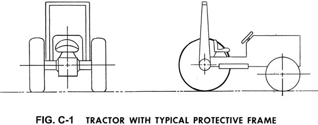
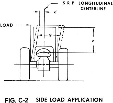
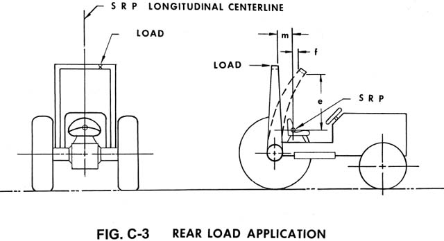
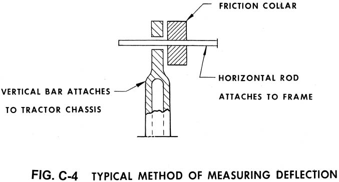
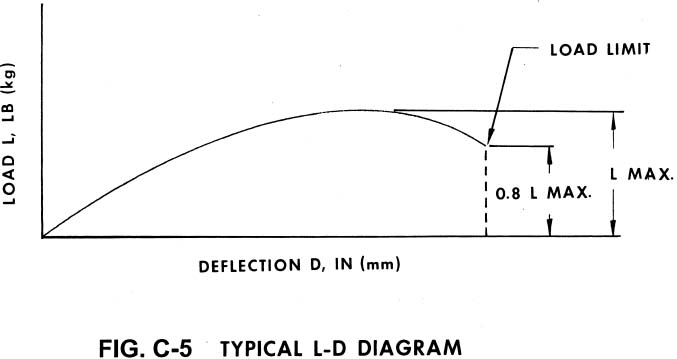
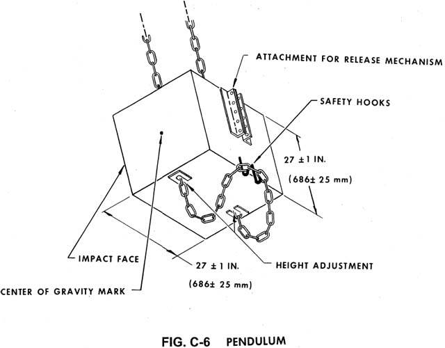
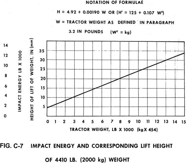
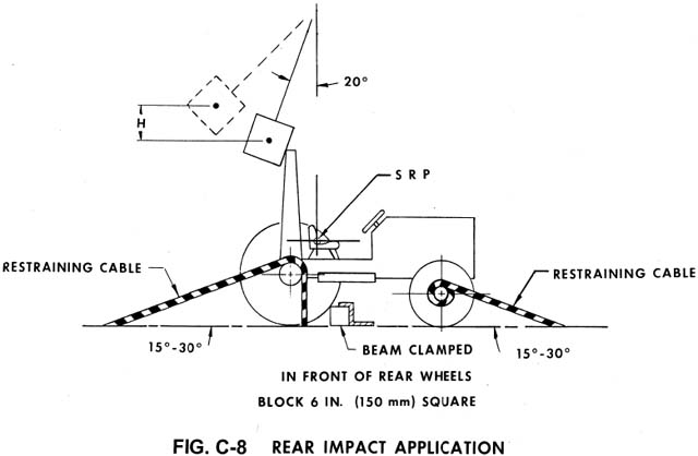
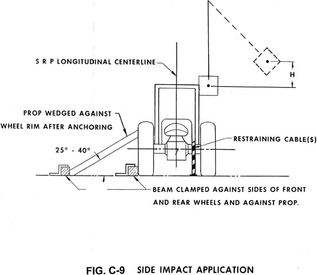
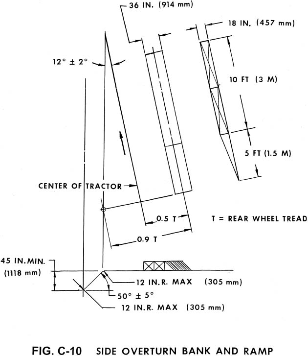
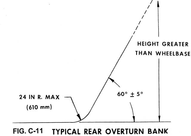
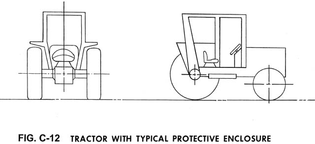
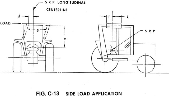
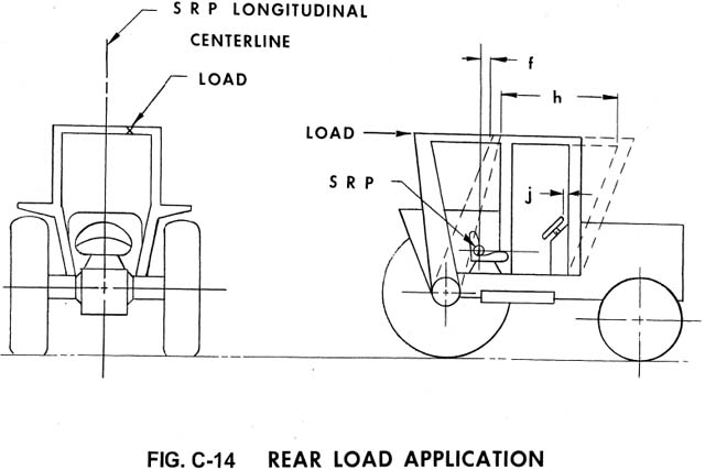
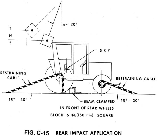
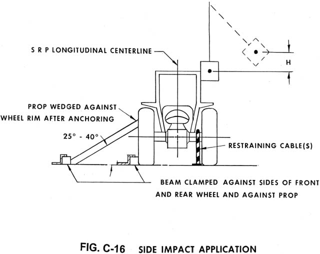
[FR Doc. 05-24462 Filed 12-28-05; 8:45 am]

BILLING CODE 4510-26-C


