Lead: Secondary Lead Smelter eTool
Engineering Controls » Local Exhaust Ventilation Diagrams
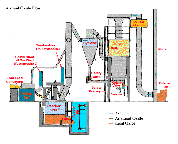
- Air and Oxide Flow
- Battery Saw Emission Control
- Blast Furnace Lead Tap Controls
- Blast Furnace Slag Tap Controls
- Bin and Hopper Ventilation
- Boot Wash Station
- Bucket Elevator Ventilation
- Central Vacuum System
- Clothes Cleaning Air Shower
- Controls for Lead Tapping and Molding
- Conveyor Belt Enclosure
- Conveyor Belt Ventilation
- Cross Section of a Typical Furnace
- Dross Pot Hood
- Dross and Skimmings Storage Ventilation
- Fixed Supplied Air Island
- Filtered, Tempered, Supplied-Air Cab
- Furnace Slag Tapping Hood
- Hood for Cup Type Surface Grinder and Wire Brushes
- Hydraulic Tuyere Punch
- Hygiene Facility
- Ingot Casting Local Exhaust Ventilation
- Mechanical Drossing Tonolli Screw Drosser
- Modified Local Exhaust Ventilation System
- Moveable Exhaust Hoods
- Portable Tool Exhaust
- Refining Kettle Enclosure
- Regenerative Sweeper
- Reverberatory Furnace
- Reverberatory Furnace (Side View)
- Scrap Barrel
- Screw Drossing
- Scrubber
- Secondary Exhaust Hoods
- Shoe Cleaning Machine
- Shredder Building
- Slag/Dross/Skim Hood
- Supplied Air Island
- Toxic Material Belt Conveying Head Pulley
- Toxic Material Conveyor Belt Loading
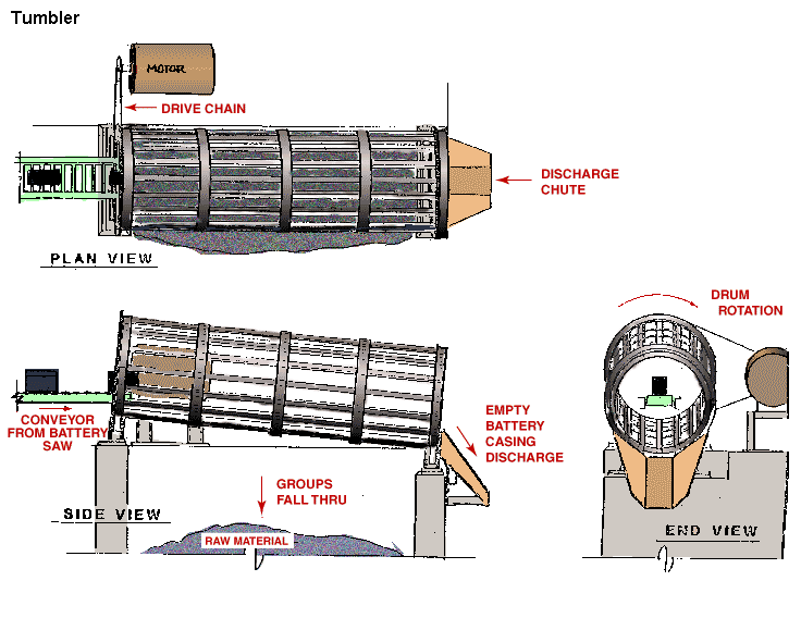
- Tumbler
- Typical System Low Volume - High Velocity
- Vacuum Truck
- Work Bench
Air and Oxide Flow
Battery Saw Emission Control
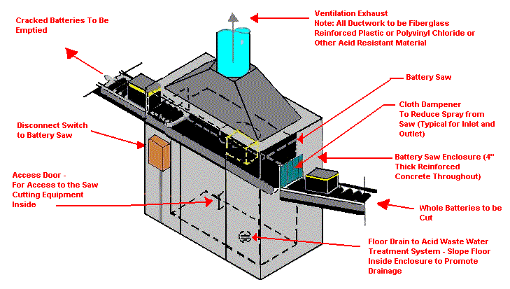
Design Characteristics:
- Provide capture velocities at openings of 350-500 FPM
- Duct velocity - 3,500
Application Tips:
- Provide drains in ductwork
- All air moving/handling equipment to be sulfuric acid resistant
Blast Furnace Lead Tap Controls
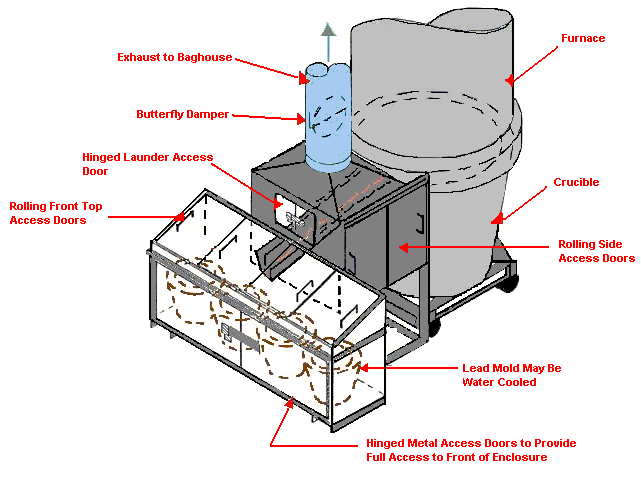
Design Characteristics:
- Enclosure to provide capture velocities at opening of 350-500 FPM
- Transport velocity in ducts greater than or equal to 4000 FPM
Blast Furnace Slag Tap Controls
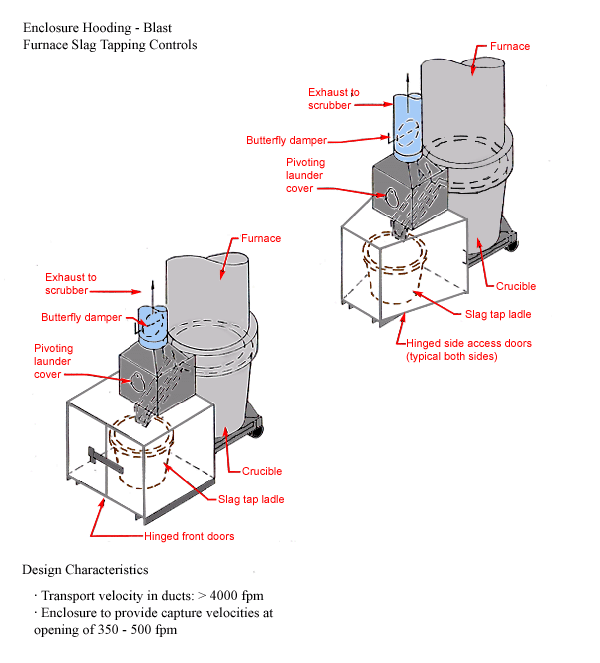
Design Characteristics
- Transport velocity in ducts: > 4000 fpm
- Enclosure to provide capture velocities at opening of 350-500 fpm
Bin and Hopper Ventilation
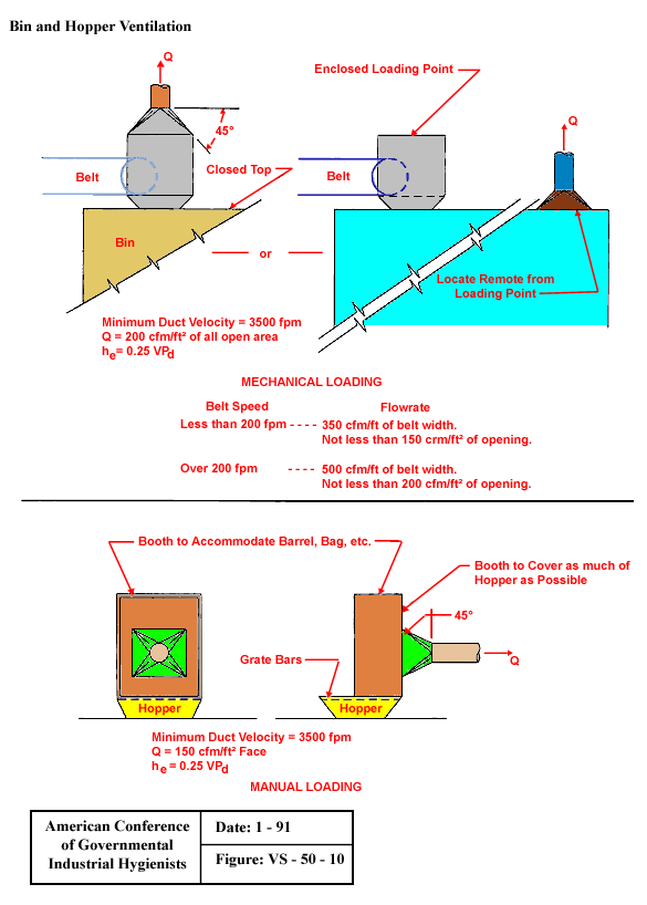
From American Conference of Governmental Industrial Hygienists (ACGIH®), Date: 1-91, Figure VS-50-10, Industrial Ventilation : A Manual of Recommended Practice, 23rd Edition. Copyright 1998. Reprinted with permission.
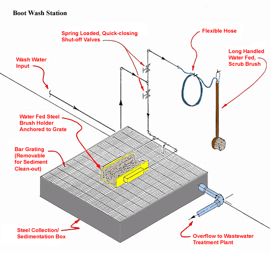
Boot Wash Station
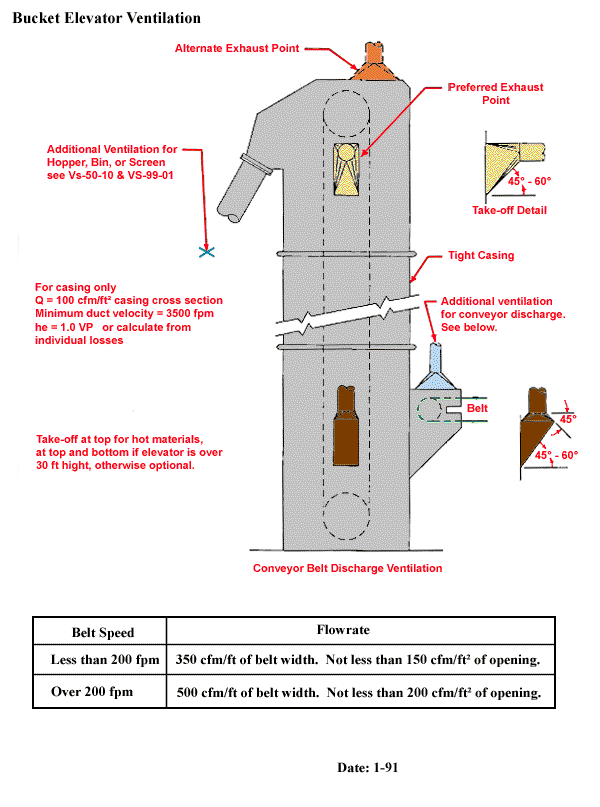
Bucket Elevator Ventilation
Central Vacuum System
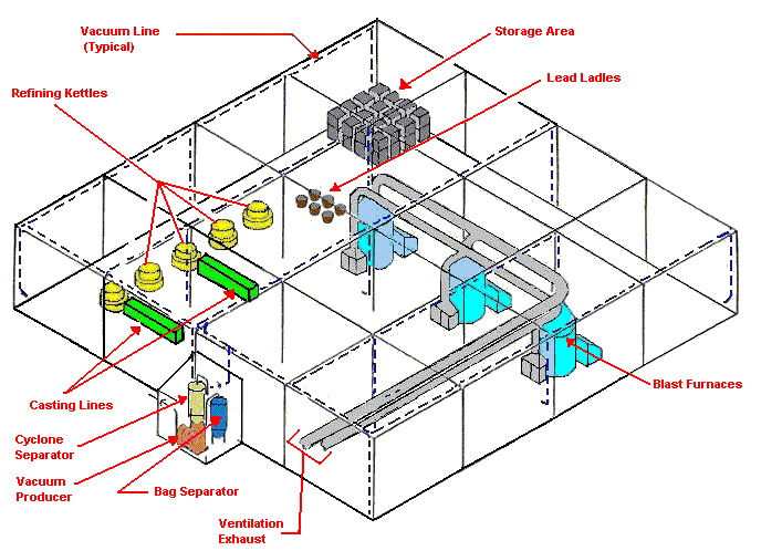
Notes
- Locate exhaust outside
- Overdesign for lead transport
- Provide ample hose and attachments at each access point
- Provide access point close to areas of high dust concentration
Clothes Cleaning Air Shower
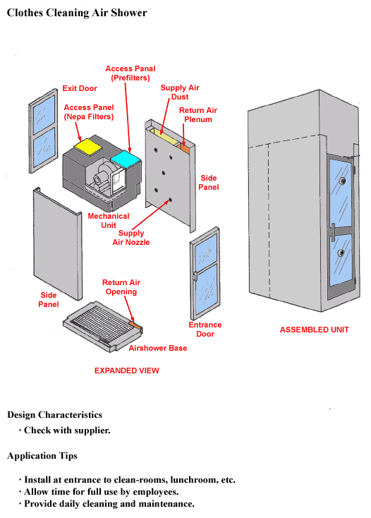
Design Characteristics
- Check with supplier.
Application Tips
- Install at entrance to clean-rooms, lunchroom, etc.
- Allow time for full use by employees.
- Provide daily cleaning and maintenance.
Controls for Lead Tapping and Molding
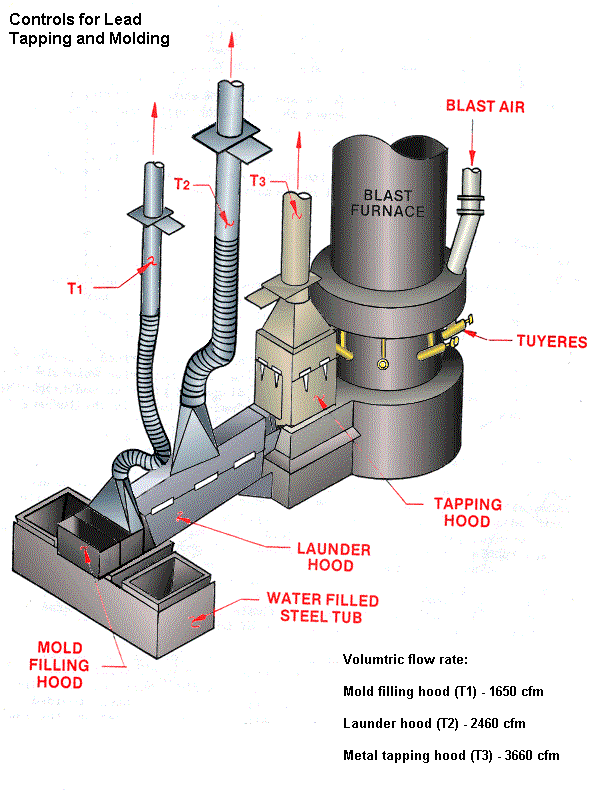
Volumtric flow rate:
Mold filling hood (T1) - 1650 cfm
Launder hood (T2) - 2460 cfm
Metal tapping hood (T3) - 3660 cfm
Proceedings of the Symposium on Occupational Health Hazard Control Technology in the Foundry and Secondary Non-Ferrous Smelting Industries, U.S. Department of Health and Human Services, NIOSH Publication No. 81-114 (1981).
Conveyor Belt Enclosure
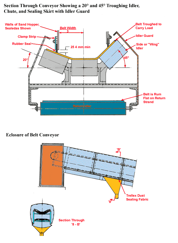
Conveyor Belt Ventilation
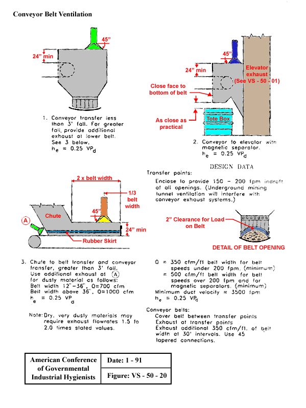
From American Conference of Governmental Industrial Hygienists (ACGIH®), Date: 1-91, Figure VS-50-20, Industrial Ventilation : A Manual of Recommended Practice, 23rd Edition. Copyright 1998. Reprinted with permission.
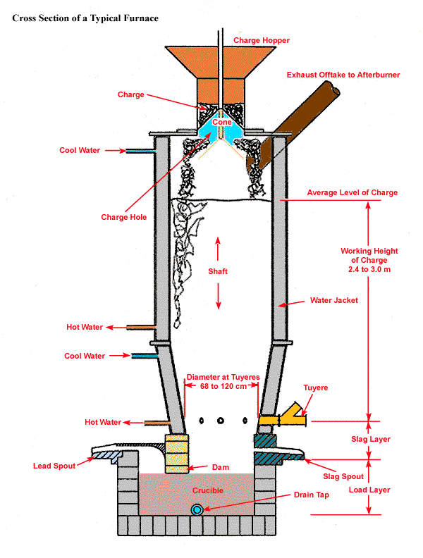
Cross Section of a Typical Furnace
Dross Pot Hood
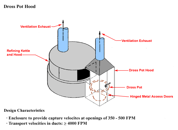
Design Characteristics
- Enclosure to provide capture velocities at openings of 350 - 500 FPM
- Transport velocities in ducts: ≥ 4000 FPM
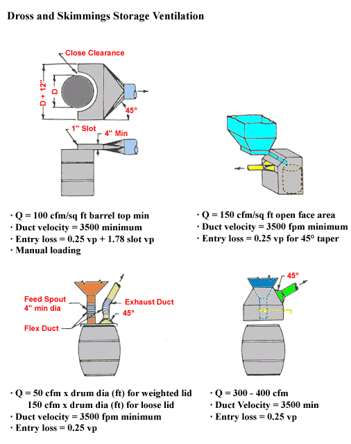
Dross and Skimmings Storage Ventilation
Fixed Supplied Air Island
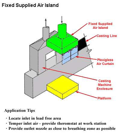
Application Tips
- Locate inlet in lead free area
- Temper inlet aid - provide thermostat at work station
- Provide outlet nozzle as close to breathing zone as possible
Filtered, Tempered, Supplied-Air Cab
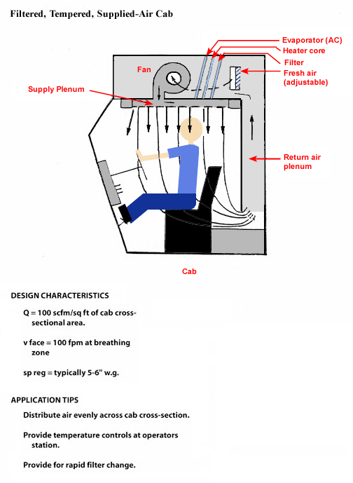
Design Characteristics
- Q = 100 scfm/sq ft of cab cross-sectional
- v face = 100 fpm at breathing zone
- sp reg = typically 5-6" w.g.
Application Tips
- Distribute air evenly across cab cross-section.
- Provide temperature controls at operators station.
- Provide for rapid filter change.
NIOSH articles:
- Improved Cab Air Inlet Location Reduces Dust Levels and Air Filter Loading Rates
- Floor Heaters Can Increase Operator's Dust Exposure in Enclosed Cabs
- Sweeping Compound Application Reduces Dust From Soiled Floors Within Enclosed Operator Cabs
Furnace Slag Tapping Hood

Design Characteristics
- Transport velocity in ducts: > 4000 fpm
- Enclosure to provide capture velocities at opening of 350-500 fpm
Hood for Cup Type Surface Grinder and Wire Brushes
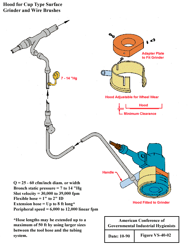
Q= 25 - 60 cfm/inch diam. or width
Bronch static pressure = 7 to 14 "Hg
Slot velocity = 30,000 to 39,000 fpm
Flexible hose = 1" to 2" ID
Extension hose = Up to 8 ft long*
Peripheral speed = 6,000 tp 12,000 inear fpm
*Hose lengths may be extended up to a maximum of 50 ft by using larger sizes between the tool hose and the tubing system.
From American Conference of Governmental Industrial Hygienists (ACGIH®), Date: 10-90, Figure VS-40-02, Industrial Ventilation : A Manual of Recommended Practice, 23rd Edition. Copyright 1998. Reprinted with permission.
Hydraulic Tuyere Punch
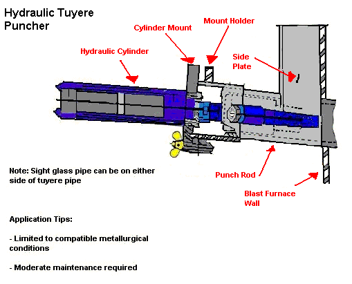
| Note: Sight glass can be on either side of tuyere pipe Application Tips
|
Hygiene Facility
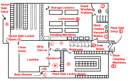
Facility Function/Description
- The facility can be entered from the street at only one point. (A)
- Street clothes are removed and clean work clothes, hardhat, and respirator are issued and donned in the street side locker room. (B)
- The employee passes through a one-way turnstile in order to get to the plant-side locker room. (C)
- The employee dons work boots and other safety gear in the plant-side locker room where they are stored. (D)
- There is only one entry to the plant. (E)
- The restroom just inside the cloak room is readily accessible during working hours. (F)
- The cloak room provides a place to store coats, hardhats, gloves and respirators during break periods. (G)
- During lunch break the employee first cleans his boots at the shoe cleaning machines (H), leaves coat and equipment in the cloak room (G), vacuums off his clothes at the vacuum stations (I), proceeds to the hand washing station where he thoroughly washes his hands (J), and finally enters the lunch room. (K)
- At the end of the shift the procedure is as follows: the employee cleans shoes (H), removes contaminated clothing in the plant side locker room (D), stores boots, etc. in plant-side lockers, turns in dirty work clothes, hardhat and respirator to laundry (L), and proceeds to the showers. (M) He then must pass through an automatic shower (N) to return to the street-side locker room (B), where he dresses and leaves the faculty. (A)
Ingot Casting Local Exhaust Ventilation
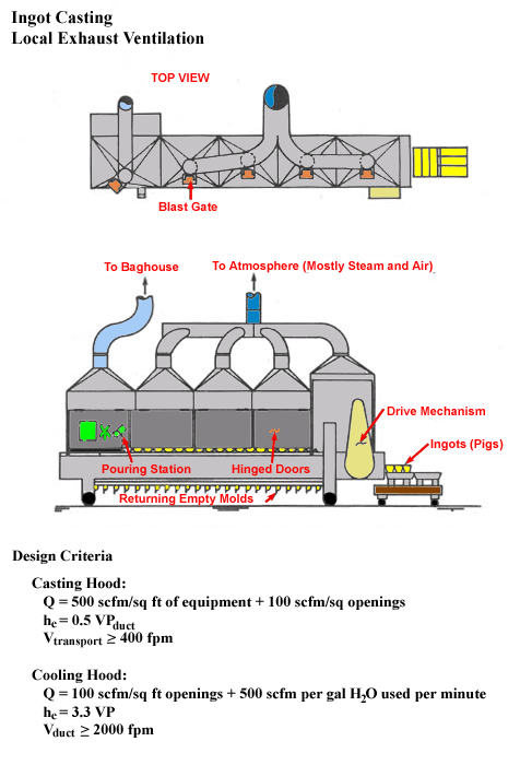
Design Criteria
Casting Hood: Q = 500 scfm/sq ft of equipment + 100 scfm/sq openings
hc = .5 VPduct
Vtransport ≥ 400 fpm
Cooling Hood:
Q = 100 scfm/sq ft openings + 500 scfm per gal H20 used per minute
hc = 3.3 VP
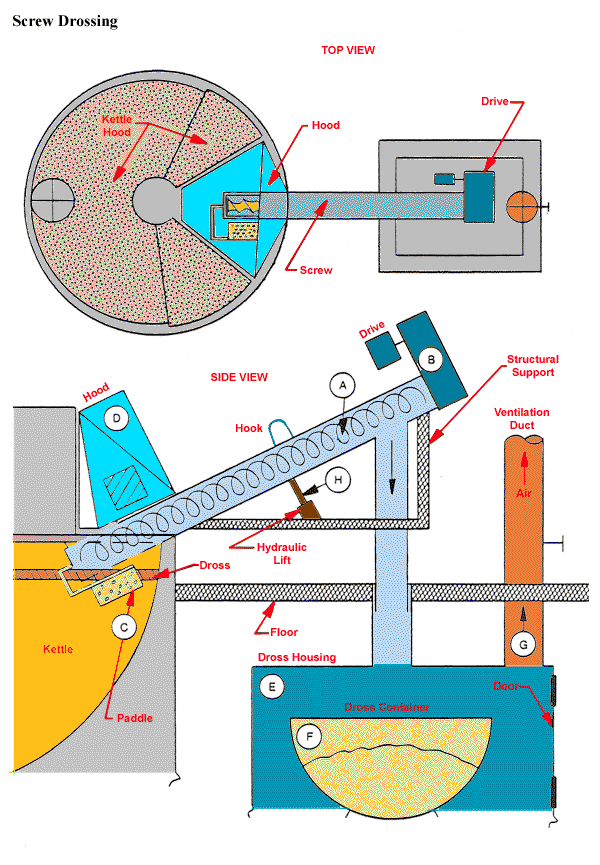
Mechanical Drossing Tonolli Screw Drosser
Modified Local Exhaust Ventilation System
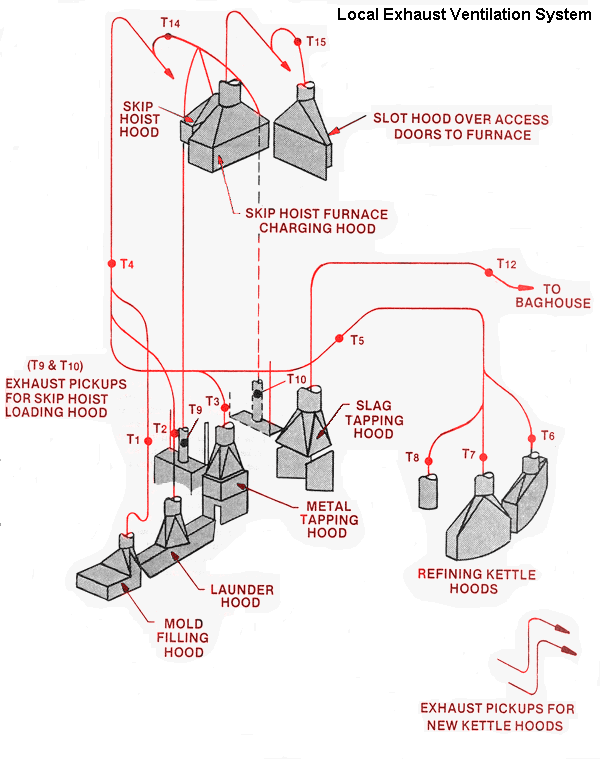
Volumetric flow rate:
(T1) Mold filling hood - 1650 cfm
(T2) Launder hood - 2460 cfm
(T3) Metal tapping hood - 3660 cfm
(T5, T6, T7, T8) Refining kettle hoods - 4700 cfm
(T9, T10) Skip hoist furnace charging hood - 12100 cfm
(T12) Slag tapping hood - 4540 cfm
(T14) Skip hoist hoods (top and bottom) - 3930 cfm
(T15) Slot hood over furnace access doors - 1940 cfm
Exhaust pickups for new kettle hoods - 2940 cfm
Discharge from slag tapping baghouse - 5000 cfm
Inlet to main exhaust fan for smelter exhaust ventilation system
- 41700 cfm
Moveable Exhaust Hoods
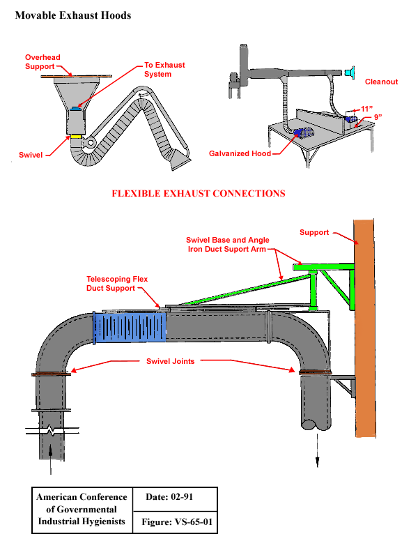
From American Conference of Governmental Industrial Hygienists (ACGIH®), Figure VS-65-01, Industrial Ventilation : A Manual of Recommended Practice, 23rd Edition. Copyright 1988. Reprinted with permission.
Portable Tool Exhaust
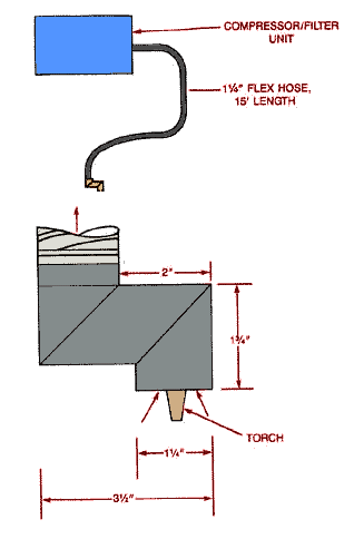
Design Criteria:
- SP is greater than or equal to 72" W.G. (inlet)
- Q = 40 CFM
- Use steel mold
- Source must be within 1" of hood
Refining Kettle Enclosure
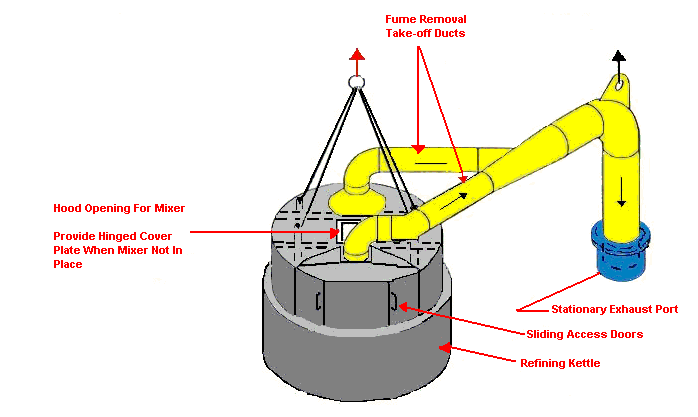
Design Characteristics:
- Volume flow rate of kettle surface area
- Dust Velocity greater than or equal to 4000 FPM
Construction Notes
- Enclose to provide at least 250 FPH face velocity at all openings
- Provide adequate lifting points for hood assembly associated ductwork
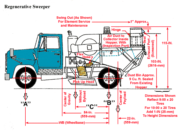
Regenerative Sweeper
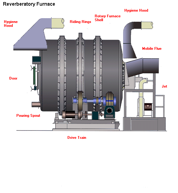
Reverberatory Furnace
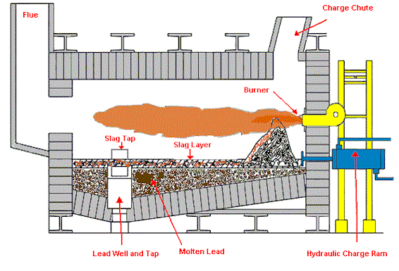
Reverberatory Furnace (Side View)
Scrap Barrel
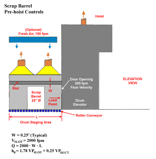
W = 0.25' (Typical)
VSLOT = 2000 fpm
Q = 2000 · W · L
h e = 1.78 VPSLOT + 0.25 VPSLOT
Screw Drossing

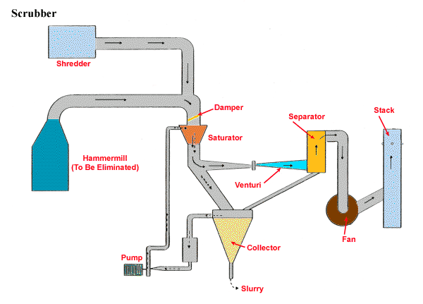
Scrubber
Secondary Exhaust Hoods
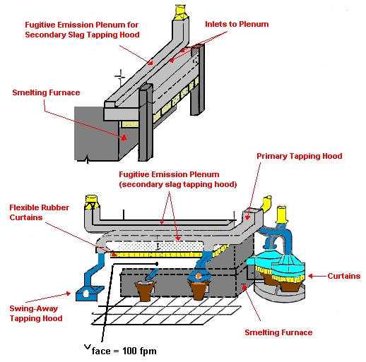
Applications Tips:
- Thoroughly characterize fugitive emissions prior to design
- Provide Make-up air
- Avoid the use of man-cooling fans
Design Characteristics:
- Q = (Natural rising velocity at hood face at 100 FPM) times surface area of hood in square feet
- V is greater or equal to 4000 FPM transport (horizontal runs)
- he = 2.2VP
Shoe Cleaning Machine
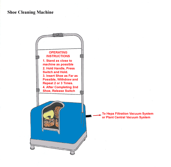
Provide exhaust ventilation, if necessary, to prevent brushes from throwing lead contaminants into operator's breathing zone.
Shredder Building
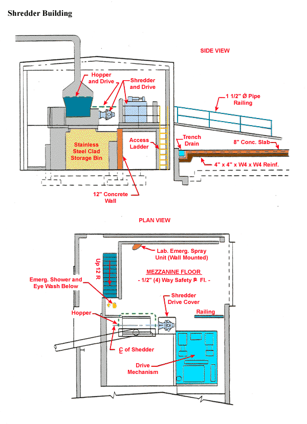
Battery Shredding and Emission Control
Application Tips:
- Provide local exhaust on shredder.
- Provide building exhaust to keep fugitive emissions inside the building.
Design Characteristics:
Q = 350 cfm/sq. ft. hood opening
Slag/Dross/Skim Hood
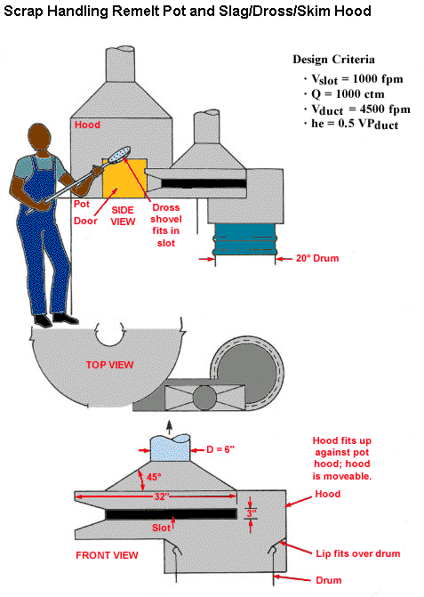
Design Criteria
- Vslot = 1000 fpm
- Q = 1000 ctm
- Vduct = 4500 fpm
- he = 0.5 VPduct
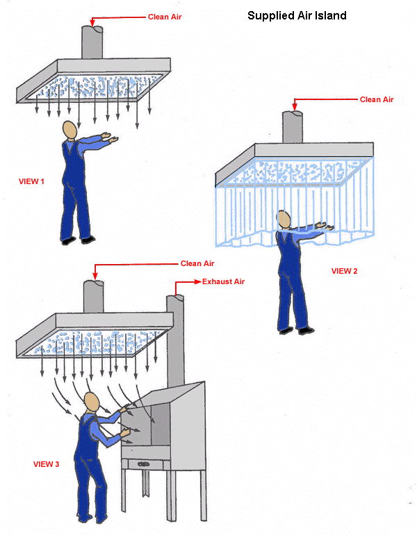
Supplied Air Island
Toxic Material Belt Conveying Head Pulley
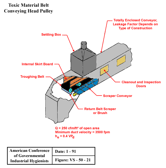
From American Conference of Governmental Industrial Hygienists (ACGIH®), Date: 1-91, Figure VS-50-21, Industrial Ventilation : A Manual of Recommended Practice, 23rd Edition. Copyright 1998. Reprinted with permission.
Toxic Material Conveyor Belt Loading
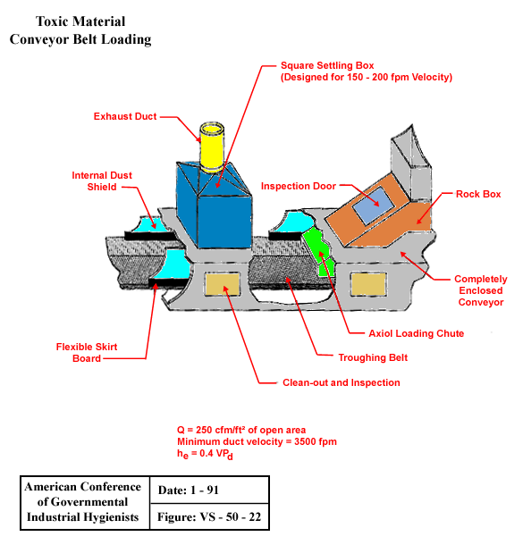
From American Conference of Governmental Industrial Hygienists (ACGIH®), Date: 1-91, Figure VS-50-22, Industrial Ventilation : A Manual of Recommended Practice, 23rd Edition. Copyright 1998. Reprinted with permission.
Tumbler
Typical System Low Volume - High Velocity
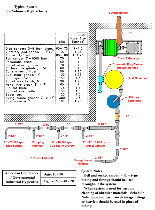
|
cfm |
I.D. Plastic Hose Size (inches) |
|
| Disk sanders 3-9 inch diam. |
60-175 |
1-1.5 |
| Vibratory pad sander - 4" x 9" |
100 |
1.25 |
| Router, 1/8" - 1" |
80-100 |
1-1.25 |
| Belt sander 3" - 4000 fpm |
70 |
1 |
| Pneumatic chisel |
60 |
1 |
| Radial wheel grinder |
70 |
1 |
| Surface die grinder, 1/4" |
60 |
1 |
| Cone wheel grinder |
90 |
1.25 |
| Cup stone grinder, 4" |
100 |
1.25 |
| Cup type brush, 6" |
150 |
1.5 |
| Radial wire brush, 6" |
90 |
1.25 |
| Hand wire brush 3" x 7" |
60 |
1 |
| Rip out knife |
175 |
1.5 |
| Rip out cast cutter |
150 |
1.5 |
| Saber saw |
120 |
1.5 |
| Swing frame grinder 2" x 18" |
380 |
2.5 |
| Saw abrasive 3" |
100 |
1.25 |
System Notes
Bell and socket, smooth - flow type
tubing and fittings should be used
throughout the system.
When System is used for vacuum
cleaning of abrasive materials. Schedule
Nol40 pipe and cast iron drainage fittings,
or heavier, should be used in place of tubing.
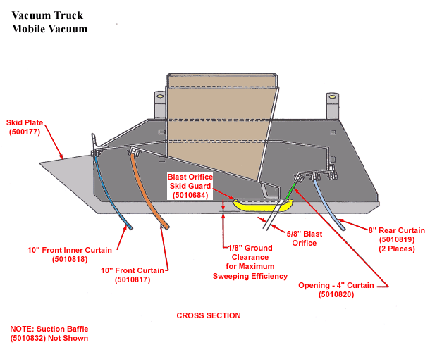
Vacuum Truck
Work Bench
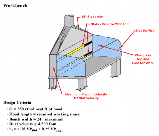
Design Criteria
- Q = 350 cfm/lineal ft of hood
- Hood length = required working space
- Bench width = 24" maximum
- Duct velocity ≥ 4,500 fpm
- hesub = 1.78 VPslot + 0.25 VPduct


