Machine Guarding eTool
Presses » Two-Hand Controls
Two-hand controls can be used as safeguarding devices in the single stoke mode of operation on part revolution clutch presses. Similar to the two-hand trip, this device keeps the operators hands away from the point of operation during the entire machine stroke.
-
Press operations requiring more than one operator must provide each operator with separate two hand controls where each set must be engaged to complete a machine stroke. The removal of a hand from any control button will stop the slide. [29 CFR 1910.217(c)(3)(vii)(a)]
-
Each two-hand control must meet the construction requirements of paragraph 29 CFR 1910.217(b)(7)(v). [29 CFR 1910.217(c)(3)(vii)(b)]
-
The safety distance (Ds) between each hand control device and the point of operation must be greater than the distance determined by the safety distance formula. [29 CFR 1910.217(c)(3)(vii)(c)]
-
Two-hand controls' position must be fixed so that only a supervisor or safety engineer is capable of relocating them. [29 CFR 1910.217(c)(3)(vii)(d)]
-
Each hand control must be protected against unintended operation and arranged by design, construction, and/or separation so that the concurrent use of both hands is required to trip the press. [29 CFR 1910.217(b)(7)(v)(a)]
-
The control system must be designed to permit an adjustment which requires concurrent pressure from both hands during the die closing portion of the stroke. [29 CFR 1910.217(b)(7)(v)(b)]
-
The control system must incorporate an anti-repeat feature. [29 CFR 1910.217(b)(7)(v)(c)]
-
The control systems must be designed to require the release of all hand controls before an interrupted stroke can be resumed. This requirement pertains only to those single stroke, two-hand controls manufactured and installed on or after August 31, 1971. [29 CFR 1910.217(b)(7)(v)(d)]
Please also see the formula used to compute the minimum safety distance on mechanical power presses to meet the ANSI B11.1 Press Safety Standard or information on stop-time measuring units.
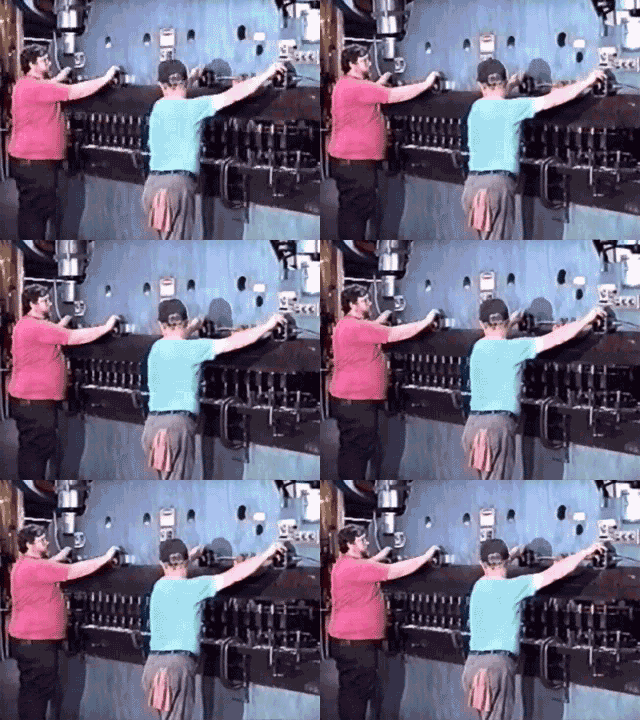
Two-hand control, as a point of operation safeguarding device for press brakes, is ideal for short-run job-shop operations. Piece parts can vary from quite small to very large.
STEP 1
By depressing the control buttons, the operator initiates the press brake stroke.
STEP 2
The operator must hold the buttons until the slide completes its downward travel. If the operator removes a hand from one of the controls, the slide will stop. In the single stroke or Hi/Lo mode, the slide will make one complete stroke.
STEP 3
In the sequence mode, the slide will automatically stop at a preset position 1/4" or less above the work piece. This position is adjustable for different feed-line heights or material thickness.
STEP 4
If the work piece is not already placed in the die, it may be inserted at this time.
STEP 5
The two-hand control or the foot switch is now re-initiated, causing the slide to continue through the bottom of the stroke and finishing at top dead center (TDC).


 Click on image to view video


