Oil and Gas Well Drilling and Servicing eTool
Well Control » Blowout Preventers

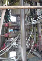
The second line of defense for the workers and the well to prevent a blowout is the group of equipment called blowout preventers (BOPs). BOPs and associated valves are installed on top of the casing head before drilling ahead after rigging up. These high-pressure safety valves and associated equipment are designed to shut off the well hole and prevent the escape of the underground fluids and prevent a blowout from occurring.
After installation, the BOP and associated valves are pressure tested to insure integrity and proper operations.
The BOP and associated equipment consists of:
BOP Stack

A BOP installation could consist of both annular and ram-type BOPs assembled into a stack. Also, there can be a kill line valve and a choke line valve.
The choke line valve is used to redirect the mud from the well bore to the choke manifold during a kick.
The kill line valve is used to direct drilling fluid to the BOP during a kick.
Annular BOP

Annular BOPs are designed to form a seal in the annular space between the drill pipe and the wellbore and are usually mounted at the top of the BOP stack.
Ram-Type BOP

Ram-type BOPs have rubber faced steel rams that come together with great force to seal the wellbore. Usually two or more ram-type BOP's are mounted in the BOP stack.
Choke Manifold

A choke manifold is a system of valves used to circulate out a kick and to circulate mud in of the proper weight. This device responds automatically to a kick and can prevent a blowout if properly installed and maintained.
Accumulator

The BOP control system, called an accumulator, provides the energy to operate the blowout preventers.
This system of consists of:
- Compressed gas bottles,
- Regulator valves,
- Pumps,
- Hydraulic reservoir,
- Control manifold, and
- Control valves.
Annular Blowout Preventer
A large valve, usually installed above the ram preventers, that forms a seal in the annular space between the pipe and well bore. If no pipe is present, it forms a seal on the well bore itself. See blowout preventer.†

#48. Ram Blowout Preventer
A blowout preventer that uses rams to seal off pressure on a hole that is with or without pipe. It is also called a ram preventer. Ram-type preventers have interchangeable ram blocks to accommodate different O.D. drill pipe, casing, or tubing.†

#22. Choke Manifold
The arrangement of piping and special valves, called chokes, through which drilling mud is circulated when the blowout preventers are closed to control the pressures encountered during a kick.†

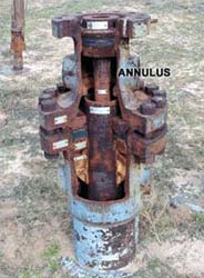
#26. Annulus
The space around a pipe in a well bore, the outer wall of which may be the wall of either the bore hole or the casing; sometimes termed the annular space.†

#8. Drill Pipe
The heavy seamless tubing used to rotate the bit and circulate the drilling fluid. Joints of pipe 30 feet long are coupled together with tool joints.†

#25. Accumulator
The storage device for nitrogen pressurized hydraulic fluid, which is used in operating the blowout preventers.†


#28. Casing Head
A heavy, flanged steel fitting connected to the first string of casing. It provides a housing for slips and packing assemblies, allows suspension of intermediate and production strings of casing, and supplies the means for the annulus to be sealed off. Also called a spool.†

#10. Blowout Preventer
One or more valves installed at the wellhead to prevent the escape of pressure either in the annular space between the casing and the drill pipe or in open hole (for example, hole with no drill pipe) during drilling or completion operations. See annular blowout preventer and ram blowout preventer.†s


